Compressing hemostasis device

A technology for hemostasis by compression and main body, applied in medical science, surgery, etc., can solve problems such as damage to compression cushions, cumbersome removal methods of compression cushions, inconvenient maintenance by operators, etc. Easy disassembly and assembly process

Inactive Publication Date: 2019-11-26
杭州迪易家医疗器械有限公司
View PDF0 Cites 0 Cited by
  • Summary
  • Abstract
  • Description
  • Claims
  • Application Information

AI Technical Summary

Problems solved by technology

[0004] The object of the present invention is to provide a compression hemostatic device to solve the problem that the compression cushion is prone to damage and often needs to be disassembled due to the long-term compression of the compression cushion during use of the existing femoral artery compression hemostat propo

Method used


Image

  • Compressing hemostasis device
  • Compressing hemostasis device
  • Compressing hemostasis device

Examples


Embodiment 1

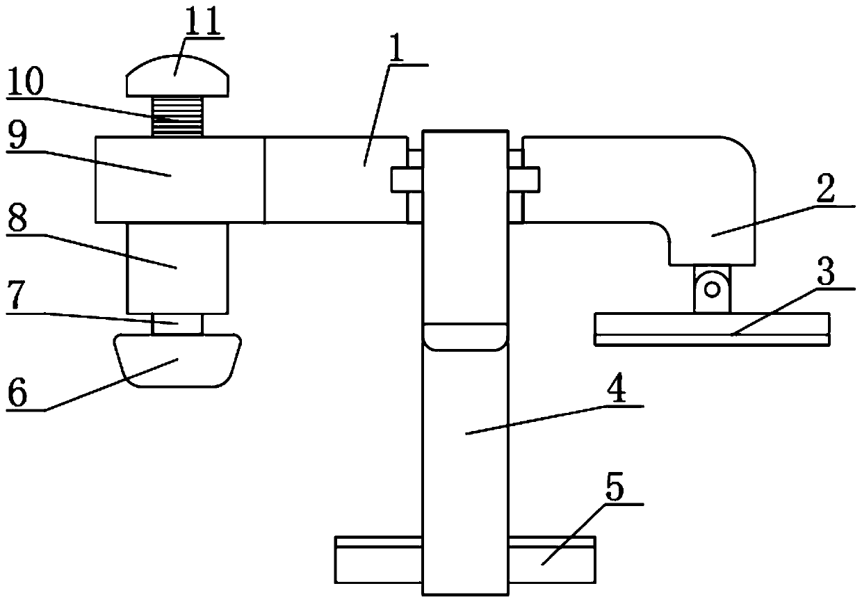
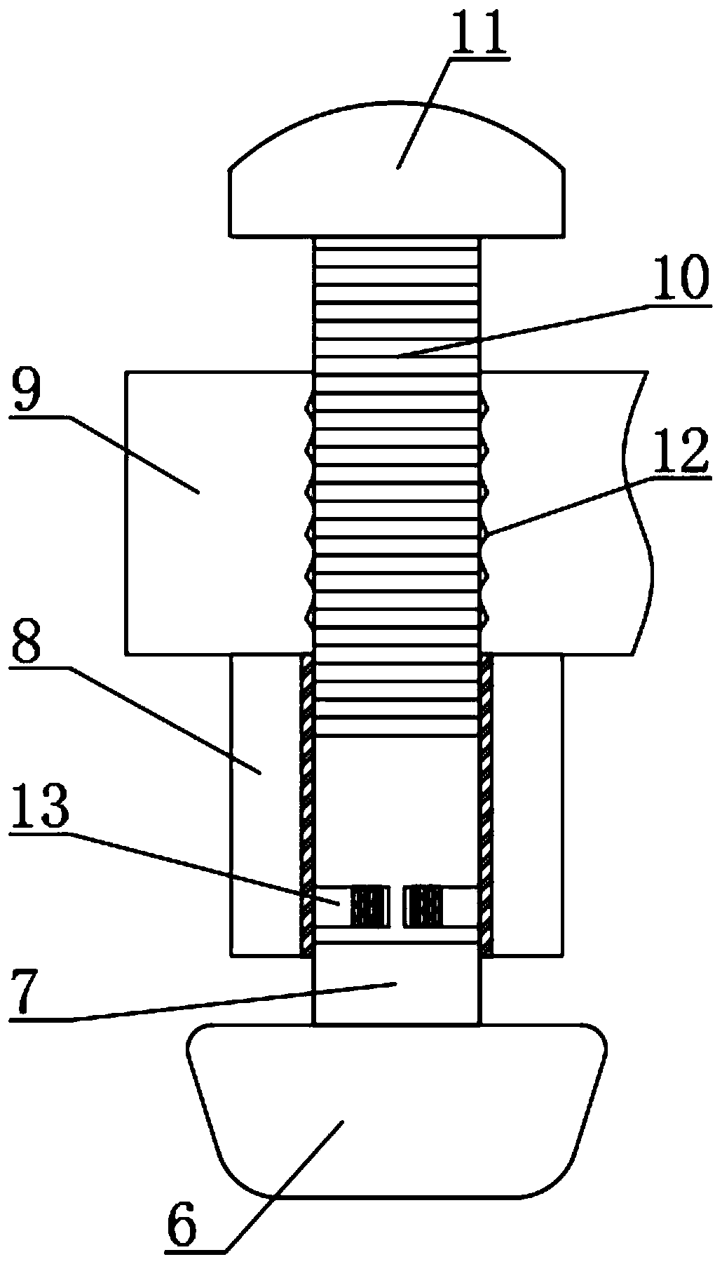
[0023] see Figure 1 to Figure 4 , the present invention provides a technical solution: a compression hemostatic device, including a main body 1, side end blocks 9 and end pieces 2 respectively arranged at both ends of the main body 1, the bottom end of the end piece 2 is connected with a fixed plate 3 through a rotating shaft, and the main body 1 The surface of the fleece belt 4 is covered with a flannelette 4, and the inner surface of the bottom end of the flannelette 4 is fixed with a fixed support pad 5 by gluing, the bottom end of the side end block 9 is welded and fixed with a bottom cover 8, and the bottom of the bottom cover 8 is provided with a pressing The cushion 6, the inside of the side end block 9 is provided with a threaded post 10, and the inside of the side end block 9 is provided with a threaded hole 12 corresponding to the threaded post 10, so that the threaded post 10 can be rotated smoothly, and the threaded post The bottom end of 10 penetrates to the insi...

Embodiment 2

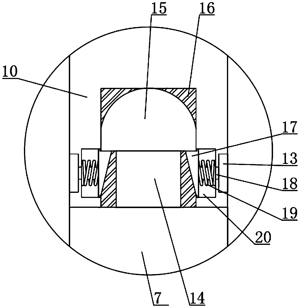
[0028] see Figure 1 to Figure 5, the present invention provides a technical solution: a compression hemostatic device, including a main body 1, side end blocks 9 and end pieces 2 respectively arranged at both ends of the main body 1, the bottom end of the end piece 2 is connected with a fixed plate 3 through a rotating shaft, and the main body 1 The surface of the fleece belt 4 is covered with a flannelette 4, and the inner surface of the bottom end of the flannelette 4 is fixed with a fixed support pad 5 by gluing, the bottom end of the side end block 9 is welded and fixed with a bottom cover 8, and the bottom of the bottom cover 8 is provided with a pressing The cushion 6, the inside of the side end block 9 is provided with a threaded post 10, and the inside of the side end block 9 is provided with a threaded hole 12 corresponding to the threaded post 10, so that the threaded post 10 can be rotated smoothly, and the threaded post The bottom end of 10 penetrates to the insid...


PUM


Abstract

The invention discloses a compressing hemostasis device. The compressing hemostasis device comprises a main body, a side end block and an end head, wherein the side end block and the end head are separately arranged at the two ends of the main body; a fixed plate is arranged at the bottom end of the end head; a flannelette tape is arranged on the surface of the main body in a sleeving manner; a fixed supporting cushion is fixed to the inner side surface of the bottom end of the flannelette tape; a bottom sleeve is welded and fixed to the bottom end of the side end block; a compressing flexiblecushion is arranged at the bottom of the bottom sleeve; a threaded column is arranged in the side end block in a penetrating manner; and through arrangement of an ejecting rod, a rotating block, a rotating groove, triangular telescopic blocks, telescopic block grooves, a pulling rod, extrusion springs, C-shaped grooves, C-shaped pulling pieces and strip-shaped anti-skid grooves, when the compressing flexible cushion is damaged in a subsequent process, the compressing flexible cushion can be detached quickly from the bottom end of the threaded column and is replaced, and the whole detachment process is very simple and convenient; and compared with complicated detachment steps of a conventional device, the compressing hemostasis device disclosed by the invention has the advantages that thedevice is very convenient for operators, and the detachment and replacement efficiency of the compressing flexible cushion is improved.

Description

technical field [0001] The invention belongs to the technical field of medical hemostasis devices, in particular to compression hemostatic devices. Background technique [0002] The femoral artery compression hemostat is a compression hemostatic device used after vascular interventional surgery. It mainly compresses the femoral artery puncture site from outside the body through mechanical pressure to promote hemostasis and healing of the puncture site. The femoral artery compression hemostat consists of the main body, rotating It is composed of a handle, a fixed plate, a fixed support pad, a compression cushion, and a fleece belt, so that medical staff can quickly get started. It is widely used in cardiology, catheterization laboratory, anesthesiology, emergency room, ICU and other departments for arterial compression and hemostasis. [0003] During the use of the existing femoral artery compression hemostat, due to the long-term pressure on the compression cushion, the comp...

Claims


Application Information

Patent Timeline
IPC IPC(8): A61B17/12
CPCA61B17/12
Inventor 王洪根
Owner 杭州迪易家医疗器械有限公司
Why Eureka
Try Eureka