Supercharge Your Innovation With Domain-Expert AI Agents!

Inflation nozzle structure for inflation sealing ring and assembly technology

An inflatable sealing ring and assembly process technology, applied in the aerospace field, can solve problems such as reliability decline, increase in bonding area, sealing failure, etc., and achieve the effects of improving product reliability, high product qualification rate, and increasing contact area.

Pending Publication Date: 2021-06-25
TIANJIN AEROSPACE ELECTROMECHANICAL EQUIP RES INST
View PDF0 Cites 0 Cited by
  • Summary
  • Abstract
  • Description
  • Claims
  • Application Information

AI Technical Summary

Problems solved by technology

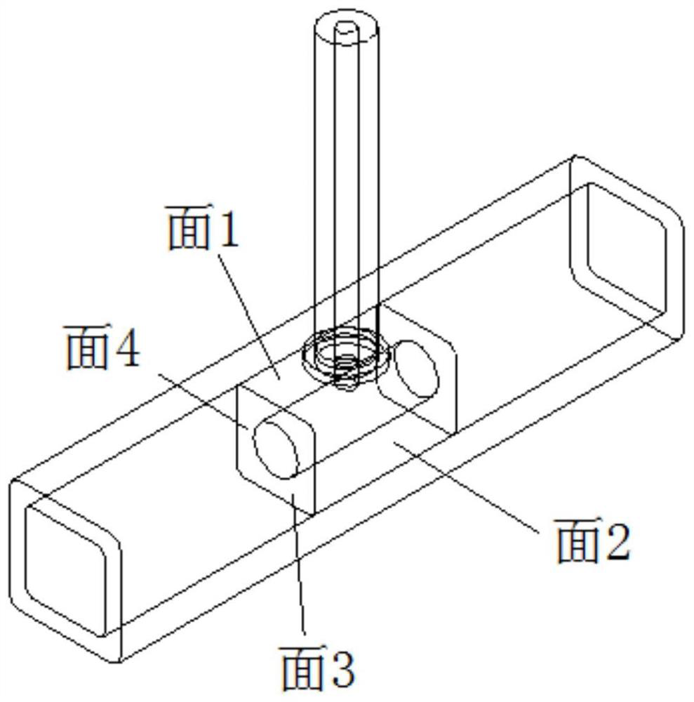
[0004] The overall structure of the metal inflation nozzle inside the existing inflation sealing ring is in an inverted "T" shape, see figure 1 The schematic diagram of the metal inflation nozzle in , the size of the covered part of the metal inflation nozzle inside the rubber strip is the same as the size of the inner cavity of the rubber strip, which can be closely fitted. When the metal inflation nozzle is combined with the rubber strip inside the rubber strip, surface 3 It is not combined with the inner surface of the rubber strip, and the other three surfaces must be combined with the rubber strip, so that the airtightness between the valve and the rubber strip can be achieved, but there is a problem with this structure: because the metal blocks on the surface 2 and surface 4 are in contact with this When inflated, the rubber surface at surface 2 and surface 4 cannot be fully stretched, and only the rubber surface at surface 3 can expand outward sufficiently, causing the inflatable sealing ring to be inflated and sealed at the inflation nozzle. The sealing gap is not as large as other places, and it is particularly easy to leak here. When the inflatable sealing ring is inflated, this area forms a weak point in the seal, which is easy to leak, or requires a large inflation pressure to seal. Increase the inflation pressure to make the seal The reliability of the ring is reduced; it must be filled with a large pressure to make the rubber strip stretch excessively relative to other places, so that the sealing requirements can be met here, but the inflation pressure is too high to make the inflatable sealing ring easy to be blown, resulting in sealing failure; Excessive pressure will also indirectly lead to the reduction of the application range of the inflatable sealing ring, and the design of three-sided bonding increases the bonding area, making it difficult to apply force evenly at the bonding point when the process is applied, and the bonding quality is extremely unstable. The joint is not sealed, and the inflatable sealing ring itself leaks air

Method used


Image

  • Inflation nozzle structure for inflation sealing ring and assembly technology
  • Inflation nozzle structure for inflation sealing ring and assembly technology
  • Inflation nozzle structure for inflation sealing ring and assembly technology

Examples


Embodiment Construction

[0039] It should be noted that, in the case of inconsistency, the embodiments and the features in the embodiments of the present invention can be combined with each other.

[0040] In describing the present invention, it should be understood that the terms "center", "longitudinal", "transverse", "upper", "lower", "front", "rear", "left", "right", " The orientations or positional relationships indicated by "vertical", "horizontal", "top", "bottom", "inner" and "outer" are based on the orientations or positional relationships shown in the drawings, and are only for the convenience of describing the present invention and Simplified descriptions, rather than indicating or implying that the device or element referred to must have a particular orientation, be constructed and operate in a particular orientation, and thus should not be construed as limiting the invention. In addition, the terms "first", "second", etc. are used for descriptive purposes only, and should not be understoo...


PUM


Abstract

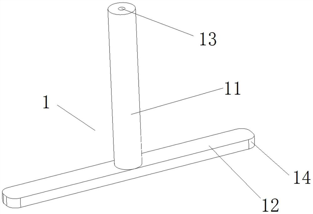
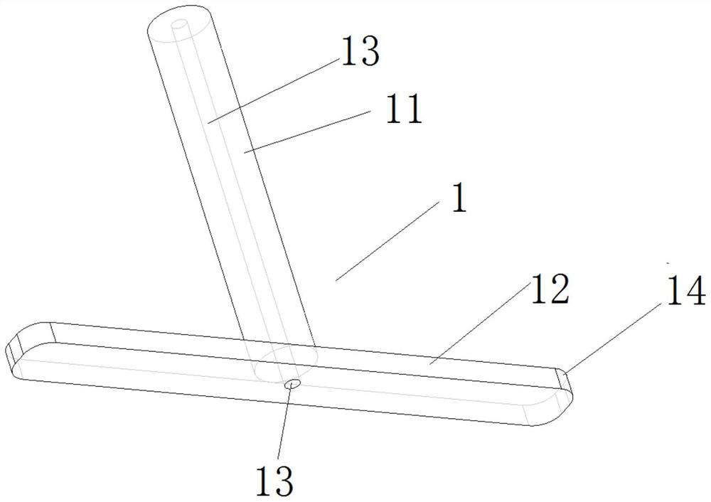
The invention provides an inflation nozzle structure for an inflation sealing ring and an assembly technology, and belongs to the field of sealing elements. The inflation nozzle structure comprises an inflation nozzle in an inverted T-shape, the inflation nozzle comprises an air inlet pipe and a fixing piece, an air inlet channel is formed in the air inlet pipe, one end of the air inlet channel communicates with the outside, the other end of the air inlet channel communicates with the interior of the inflation sealing ring, the fixing piece is arranged on the outer ring of the lower end of the air inlet pipe and embedded in the thickness layer of the inflation sealing ring, the lower end face of the air inlet pipe coincides with the inner wall of the inflation sealing ring, and the inflating nozzle and the inflation sealing ring are combined and fixed into a whole. According to the inflation nozzle structure, tearing force at the joint surface is reduced, and the air tightness of the joint surface is protected.

Description

technical field [0001] The invention belongs to the aerospace field and relates to an inflatable sealing ring, in particular to an inflating nozzle structure and an assembly process for the inflatable sealing ring. Background technique [0002] The inflatable sealing ring, also known as the air bag, is hollow inside and has at least one filling (discharging) nozzle. In the natural state, the retractable part of the sealing ring is hidden in the groove. Deformation occurs under the action of internal pressure, and the middle part swells outwards to closely contact with the other sealing surface, thus playing a sealing role. When the sealing state needs to be released, the high-pressure gas in the sealing ring is discharged through the gas nozzle, and the expansion part is automatically retracted into the groove by the elastic action of the rubber, and is separated from the sealing surface. It is mostly used for sealing the gap between large hatches and hatches or often Open ...

Claims


Application Information

Patent Timeline
Patent Type & Authority Applications(China)
IPC IPC(8): F16J15/46B29C35/02
CPCB29C35/02F16J15/46
Inventor 庞学丰王瑞文席晋东钤晓光
Owner TIANJIN AEROSPACE ELECTROMECHANICAL EQUIP RES INST
Features
  • R&D
  • Intellectual Property
  • Life Sciences
  • Materials
  • Tech Scout
  • Unparalleled Data Quality
  • Higher Quality Content
  • 60% Fewer Hallucinations
Learn More