Sternum fixing device for cardiac surgery
A fixation device and heart surgery technology, applied in surgery, medical science, etc., can solve the problems of wound enlargement, wound tearing, increasing time consumption, etc., achieve the effect of reducing wounds, reducing tearing force, and improving work efficiency
- Summary
- Abstract
- Description
- Claims
- Application Information
AI Technical Summary
Problems solved by technology
Method used
Image

Examples
Embodiment 1
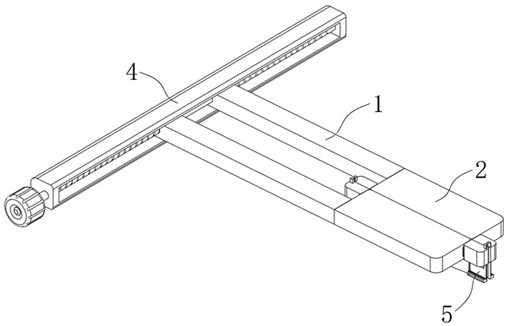
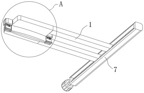
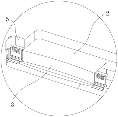
[0031] see Figure 1-Figure 6 , a sternum fixation device for cardiac surgery in the figure, including a driving device 4, a clamping device 5, a pulling device 6 and two groups of support rods 1, the two groups of support rods 1 are fixedly connected with a device box 2, and the device box 2 is fixedly connected with a support plate 3 for supporting and fixing the sternum. The driving device 4 is installed on the supporting rod 1 to drive the two groups of supporting rods 1 to slide and open to both sides to complete the supporting and fixing of the sternum. The clamping device 5 is installed At both ends of the device box 2, it is used to clamp and fix the muscles and skins at both ends of the patient's chest opening during the initial stage of the support plate 3 sliding to both sides. 3. When the sternum is continuously stretched to both sides, the linkage rotates and pulls the clamping device 5 inward to a certain extent, thereby reducing the tearing force on both sides of ...
Embodiment 2
[0036] see Figure 7-Figure 9 and Figure 12 The second embodiment will be described. The present embodiment will further describe the first embodiment. The clamping device 5 in the figure includes two sets of clockwork shafts 17 connected to the device slot 15. The clockwork shaft 17 is connected with the device slot 15. The rotating block 18 is rotatably connected, the rotating block 18 is fixedly connected with a device block 19, a lifting groove 20 is opened in the device block 19, and a first clamping block 21 and a second clamping block 22 are slidably connected in the lifting groove 20. The bottoms of the second clamping blocks 22 are fixedly connected with a plurality of plug pins 51 , the first clamping block 21 is fixedly connected with a first rack 23 slidably connected with the lifting groove 20 , and the second clamping block 22 is fixedly connected with The second rack 24 is slidably connected with the lifting slot 20. The lifting slot 20 is rotatably connected ...
Embodiment 3
[0041] see Figure 10-Figure 12 The third embodiment will be described. This embodiment will further describe the first embodiment. The pulling device 6 in the figure includes a plurality of second tooth blocks 39 , a driving slot 40 is formed in the rotating block 18 , and a plurality of second tooth blocks 39 , etc. The distance is distributed and is slidably connected with the driving slot 40. The driving slot 40 is slidably connected with a lifting plate 41 that is fixedly connected to the second clamping block 22, and the second tooth block 39 is provided with a slope 42 that is slidingly connected to the lifting plate 41. The device slot 15 is provided with a rotating member 43 for interlocking the rotating block 18 to rotate when the second toothed block 39 slides out of the driving slot 40 .
[0042] see Figure 10-Figure 12 , the rotating member 43 in the figure includes a second belt 44, a first rotating shaft 45 and a second rotating shaft 46 are rotatably connecte...
PUM
 Abstract
Description
Claims
Application Information