
Optical filter structure and optical filter

A filter structure and optical filter technology, applied in optics, optical components, instruments, etc., can solve the problems of poor practicability, inability to meet high stability, high integration and easy control, and large volume of tunable optical filters

Active Publication Date: 2022-08-02
INST OF SEMICONDUCTORS - CHINESE ACAD OF SCI
View PDF0 Cites 0 Cited by
  • Summary
  • Abstract
  • Description
  • Claims
  • Application Information

AI Technical Summary

Problems solved by technology

Bandwidth tunable optical filters in the related art often adopt structures such as multi-stage Mach-Zehnder (MZ, MachZehnder) and high-order microring resonators. and control algorithm complex, poor stability and other issues
[0004] In the process of realizing the present disclosure, it is found that the existing tunable optical filters are poor in practicability and cannot meet the requirements of high stability, high integration, and easy control at the same time

Method used


Image

  • Optical filter structure and optical filter
  • Optical filter structure and optical filter
  • Optical filter structure and optical filter

Examples


Embodiment Construction

[0022] Hereinafter, embodiments of the present disclosure will be described with reference to the accompanying drawings. It should be understood, however, that these descriptions are exemplary only, and are not intended to limit the scope of the present disclosure. In the following detailed description, for convenience of explanation, numerous specific details are set forth in order to provide a thorough understanding of the embodiments of the present disclosure. It will be apparent, however, that one or more embodiments may be practiced without these specific details. Also, in the following description, descriptions of well-known structures and techniques are omitted to avoid unnecessarily obscuring the concepts of the present disclosure.

[0023] The terminology used herein is for the purpose of describing particular embodiments only and is not intended to limit the present disclosure. The terms "comprising", "comprising" and the like as used herein indicate the presence o...


PUM


Abstract

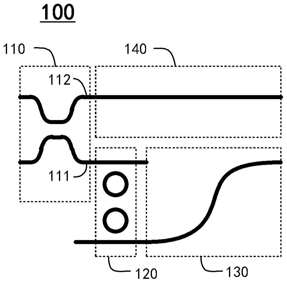
The present disclosure provides an optical filter structure, including: an optical switch including a first output end and a second output end, the optical switch is used for receiving an optical signal and switching the transmission path of the optical signal; a second-order micro-ring optical filter unit , connected with the first output end of the optical switch, used for filtering the optical signal; the first waveguide, connected with the output end of the second-order micro-ring optical filter unit, used for transmitting the filtered optical signal; and the second A waveguide, connected to the second output end of the optical switch, for transmitting the unfiltered optical signal. In addition, the present disclosure also provides an optical filter constructed by using the above-mentioned optical filter structure through multi-stage cascading.

Description

technical field [0001] The present disclosure relates to the technical field of optical fiber communication, and more particularly, to an optical filter structure and an optical filter constructed by using the above-mentioned optical filter structure through multi-stage cascade. Background technique [0002] Optical filters can directly filter microwave signals in high frequency bandwidth, and are essential devices in transmitters, receivers and switching nodes of wavelength division multiplexing (WDM) networks. Applications such as lidar and astronomical systems also play an irreplaceable role. [0003] The ability to select the target frequency band is an important indicator of the optical filter applied to microwave photonic signal processing, which requires the optical filter to have bandwidth tunable characteristics, and under certain conditions, low insertion loss, flat top and Box filter spectral line response with steep band edges. Bandwidth tunable optical filters...

Claims


Application Information

Patent Timeline
Patent Type & Authority Patents(China)
IPC IPC(8): G02B6/293
CPCG02B6/29395G02B6/29343G02B6/2934
Inventor 牛佳琪付鑫张磊杨林
Owner INST OF SEMICONDUCTORS - CHINESE ACAD OF SCI
Learn More