
Fixing structure of switching devices and installation method of switching devices

A technology of switching devices and fixed structures, applied in the field of power modules, can solve the problems of poor vibration resistance of plastic brackets, unfavorable fixing of switching device modules, and many mechanical parts

Pending Publication Date: 2021-06-25
UNITED AUTOMOTIVE ELECTRONICS SYST
View PDF0 Cites 0 Cited by
  • Summary
  • Abstract
  • Description
  • Claims
  • Application Information

AI Technical Summary

Problems solved by technology

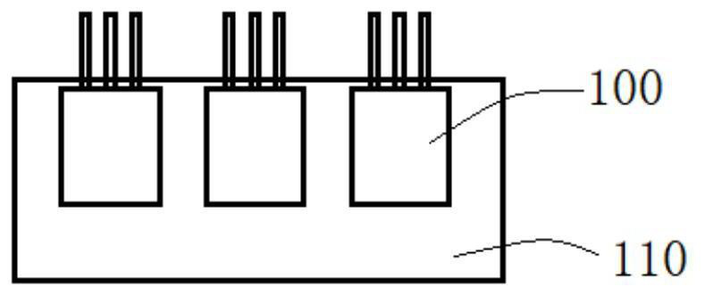
However, the defects of this design have the following points: 1) each product requires at least two plastic brackets, resulting in many mechanical parts and a significant increase in cost; fixed to the PCB during the process; and 3) the plastic bracket has poor vibration resistance, etc.

Method used


Image

  • Fixing structure of switching devices and installation method of switching devices
  • Fixing structure of switching devices and installation method of switching devices
  • Fixing structure of switching devices and installation method of switching devices

Examples


Embodiment Construction

[0028] The technical solutions in the present invention will be clearly and completely described below in conjunction with the accompanying drawings. Apparently, the described embodiments are part of the embodiments of the present invention, not all of them. Based on the embodiments of the present invention, all other embodiments obtained by persons of ordinary skill in the art without making creative efforts belong to the protection scope of the present invention.

[0029] It should be understood that the invention can be embodied in different forms and should not be construed as limited to the embodiments set forth herein. Rather, these embodiments are provided so that this disclosure will be thorough and complete, and will fully convey the scope of the invention to those skilled in the art. In the drawings, the size and relative sizes of layers and regions may be exaggerated for clarity, and like reference numerals designate like elements throughout. It will be understood ...


PUM


Abstract

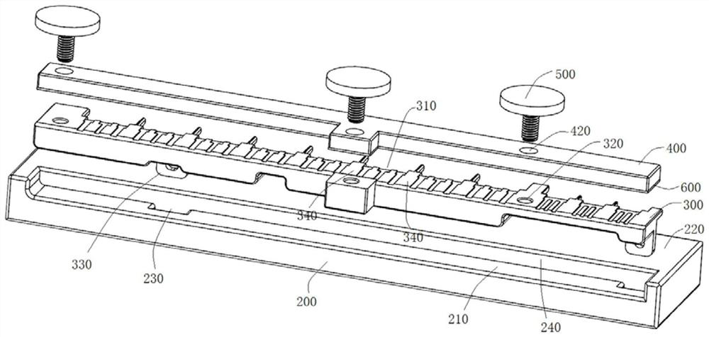
The invention relates to a fixing structure of switching devices and relates to a power conversion device. The fixing structure comprises a bottom plate, a switching device positioning plate and a cover plate; the bottom plate and the switching device positioning plate are assembled together; the switching device positioning plate comprises a plurality of spacers; the spacers are located on the side, away from the bottom plate, of the switching device positioning plate; a plurality of switching device pin accommodating grooves are formed in the main body part of the switching device positioning plate between two adjacent spacers and are used for accommodating pins of switching devices; the cover plate is pressed on the switching device positioning plate so as to press the pins of the switching device in the switching device pin accommodating grooves, and therefore, a plurality of switching devices form a switching device module.

Description

technical field [0001] The invention relates to a power module, in particular to a fixing structure of a switching device. Background technique [0002] With the development of the automobile industry, the requirements for the miniaturization of auto parts are getting higher and higher, and the integration of parts is required to be higher and higher, so modular installation has become a common method. [0003] However, as an important power device of a charger in an automobile, switching devices are numerous in number and generate a large amount of heat. Therefore, the stable installation and heat dissipation of the switching device are important indicators of the charger. In addition, the installation position of the switch device needs to be controlled more accurately, otherwise problems such as too close distance or uneven pressing force may easily occur. [0004] see figure 1 , figure 1 It is a schematic diagram of a fixed structure of a switching device in the prio...

Claims


Application Information

Patent Timeline
IPC IPC(8): H01H9/02H01H9/52
CPCH01H9/02H01H9/52
Inventor 袁涛许晨晖戚本钰张宏亮谢卫其赵艳龙
Owner UNITED AUTOMOTIVE ELECTRONICS SYST
Learn More