Spatial quasi co-location conflict handling

A quasi-co-location and space technology, applied in the direction of synchronization device, separation device of transmission path, wireless communication, etc.

Pending Publication Date: 2021-06-25
QUALCOMM INC
0 Cites 0 Cited by

AI-Extracted Technical Summary

Problems solved by technology

However, in some cases the UE may not support multiple spatial QCL ...

Method used

[0064] In some examples, base station 105 or UE 115 may be equipped with multiple antennas, which may be used to employ techniques such as transmit diversity, receive diversity, multiple-input multiple-output (MIMO) communication, or beamforming. For example, a wireless communication system may employ a transmission scheme between a transmitting device (eg, base station 105) and a receiving device (eg, UE 115), where the transmitting device is equipped with multiple antennas and the receiving device is equipped with one or more antennas. MIMO communication can employ multipath signal propagation to increase spectral efficiency by sending or receiving multiple signals via different spatial layers (which may be referred to as spatial multiplexing). For example, multiple signals may be transmitted by a transmitting device via different antennas or different combinations of antennas. Similarly, multiple signals may be received by a receiving device via different antennas or different combinations of antennas. Each of the multiple signals may be referred to as a separate spatial stream, and may carry bits associated with the same data stream (eg, the same codeword) or different data streams. Different spatial layers may be associated with different antenna ports for channel measurement and reporting. MIMO techniques include single-user MIMO (SU-MIMO) for transmitting multiple spatial layers to the same receiving device, and multi-user MIMO (MU-MIMO) for transmitting multiple spatial layers to multiple devices.
[0070] In some cases, wireless communication system 100 may be a packet-based network that operates according to a layered protocol stack. In the user plane, communications at the bearer or Packet Data Convergence Protocol (PDCP)...

Abstract

Methods, systems, and devices for wireless communications are described. User equipment (UE) may receive a carrier aggregation (CA) configuration for communications on a set of cells. The UE may determine that signals transmitted on the set of cells may be spatially quasi co-located based on the CA configuration and a predetermined relationship rule. The UE may determine that the signals are spatially co-located based on receiving multiple synchronization signal blocks (SSBs) that have a same SSB index, receiving a common SSB, assuming that an SSB and reference signals sourced by the SSB are spatially quasi co-located, receiving a signal from a particular cell of the set of cells, or receiving a common spatial QCL relationship during a configured period of time. Once the spatial QCL relationship is determined, the UE may receive the signals transmitted on the set of cells based on the spatial QCL relationship.

Application Domain

Synchronisation arrangementTransmission path division +3

Technology Topic

Carrier signalTelecommunications +4

Image

  • Spatial quasi co-location conflict handling
  • Spatial quasi co-location conflict handling
  • Spatial quasi co-location conflict handling

Examples

  • Experimental program(1)

Example Embodiment

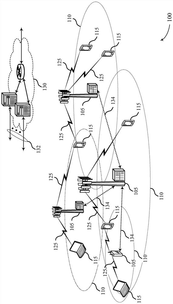
[0043] In some wireless communication systems, a base station may communicate with user equipment (UE) using multiple antennas. Additionally, the base station may include multiple cells and communicate with the UE according to a carrier aggregation (CA) configuration that uses multiple antennas to communicate over the multiple cells. In some cases, the CA configuration may include communications on multiple cells from multiple antennas on one or more respective base stations. Based on the use of multiple antennas, a quasi-co-located (QCL) relationship may exist between one or more antenna ports corresponding to the multiple antennas. The QCL relationship may indicate that the spatial parameters of a transmission on one antenna port may be inferred from the spatial parameters of another transmission on a different antenna port.
[0044] However, for in-band CA configuration, the UE may not simultaneously support multiple spatial QCL relationships within or across cells. For example, the spatial QCL can be tied to different antenna port (eg, antenna panels, antennas, etc.) selections or adjustments such that supporting multiple spatial QCL relationships would require additional hardware cost at the UE. Additionally, even if the QCL of the second signal is sourced by the first signal, the UE may assume different spatial QCL relationships for the first signal and the second signal. For example, a synchronization signal block (SSB) transmission may be a source QCL for reference signal transmissions (eg, channel state information reference signal (CSI-RS), tracking reference signal (TRS), etc.), indicating that the two transmissions are quasi- Co-located, but the UE may still assume that the two transmissions have different QCL relationships based on the UE not supporting multiple spatial QCL relationships simultaneously.
[0045] To overcome the limitation on supporting one spatial QCL relationship for CA configuration, the UE may apply a single spatial QCL relationship across multiple cells of CA configuration based on predetermined relationship rules. For example, the UE may assume the same spatial QCL relationship across cells in a CA configuration that transmits SSBs with the same SSB index. Additionally or alternatively, the UE may assume the same spatial QCL relationship across cells in a CA configuration that transmit the same SSB with cross-carrier QCL indications. In some cases, the UE may determine the same spatial QCL relationship based on the assumption that the SSB is spatially quasi-co-located with the reference signal sourced by the SSB. Additionally or alternatively, the UE may determine the same based on receiving signals from a specific cell (eg, a primary cell (PCell), a primary secondary cell (PSCell), or the cell with the smallest serving index within the in-band CA) among multiple cells. Spatial QCL relationship. In some cases, UE 115 may determine which signal to use based on receiving the signal during a time period (wherein the signals are spatially quasi-co-located according to a common spatial QCL relationship) and selecting a signal during the time period to determine the same spatial QCL relationship. Once the spatial QCL relationship is determined, the UE 115 may receive signals sent on the set of cells based on the spatial QCL relationship.
[0046] Certain aspects of the subject matter described herein can be implemented to achieve one or more advantages. The described techniques may support improvements in communications using multiple component carriers to communicate at a UE, which may improve reliability and throughput, and mitigate the effects of delay between communications on different component carriers, among other advantages. Accordingly, supported technologies may include improved network operation and, in some examples, increased network efficiency, among other benefits.
[0047] Aspects of the present disclosure were originally described in the context of a wireless communication system. Additional wireless communication systems and process flows are provided to illustrate aspects of the present disclosure. Aspects of the present disclosure are further illustrated and described with reference to device diagrams, system diagrams, and flow diagrams related to spatial QCL conflict handling.
[0048] figure 1 An example of a wireless communication system 100 supporting spatial QCL collision handling in accordance with aspects of the present disclosure is shown. Wireless communication system 100 includes base station 105 , UE 115 and core network 130 . In some examples, wireless communication system 100 may be a Long Term Evolution (LTE) network, an LTE-Advanced (LTE-A) network, an LTE-A Pro network, or a New Radio (NR) network. In some cases, the wireless communication system 100 may support enhanced broadband communication, ultra-reliable (ie, mission-critical) communication, low-latency communication, or communication with low-cost and low-complexity devices.
[0049] Base station 105 may wirelessly communicate with UE 115 via one or more base station antennas. The base stations 105 described herein may include or may be referred to by those skilled in the art as base transceiver stations, radio base stations, access points, radio transceivers, Node Bs, eNodeBs (eNBs), Next Generation Node Bs, or Gigabit Node B (any of which may be referred to as a gNB), Home Node B, Home eNodeB, or some other suitable terminology. The wireless communication system 100 may include different types of base stations 105 (eg, macro cell base stations or small cell base stations). The UEs 115 described herein are capable of communicating with various types of base stations 105 and network equipment including macro eNBs, small cell eNBs, gNBs, relay base stations, and the like.
[0050] Each base station 105 may be associated with a particular geographic coverage area 110 in which communication with various UEs 115 is supported. Each base station 105 may provide communication coverage for a corresponding geographic coverage area 110 via a communication link 125, and the communication link 125 between the base station 105 and the UE 115 may utilize one or more carriers. The communication link 125 shown in the wireless communication system 100 may include uplink transmissions from the UE 115 to the base station 105 or downlink transmission from the base station 105 to the UE 115 . Downlink transmissions may also be referred to as forward link transmissions, and uplink transmissions may also be referred to as reverse link transmissions.
[0051] The geographic coverage area 110 of the base station 105 may be divided into sectors that form only a portion of the geographic coverage area 110, and each sector may be associated with a cell. For example, each base station 105 may provide communication coverage for macro cells, small cells, hotspots, or other types of cells, or various combinations of the foregoing. In some examples, base stations 105 may be mobile and thus provide communication coverage for a moving geographic coverage area 110 . In some examples, different geographic coverage areas 110 associated with different technologies may overlap, and overlapping geographic coverage areas 110 associated with different technologies may be supported by the same base station 105 or by different base stations 105 . The wireless communication system 100 may include, for example, a heterogeneous LTE/LTE-A/LTE-A Pro or NR network, where different types of base stations 105 provide coverage for various geographic coverage areas 110.
[0052] The term "cell" refers to a logical communication entity used to communicate with the base station 105 (eg, via a carrier), and may be associated with an identifier (eg, physical) used to distinguish neighboring cells operating via the same or different carriers. Cell Identifier (PCID), Virtual Cell Identifier (VCID)) are associated. In some examples, a carrier may support multiple cells, and different cells may be based on different protocol types (eg, Machine Type Communication (MTC), Narrowband Internet of Things (NB-IoT), Enhanced Mobile Broadband (eMBB), etc.) is configured where different protocol types can provide access for different types of devices. In some cases, the term "cell" may refer to a portion (eg, a sector) of a geographic coverage area 110 over which a logical entity operates.
[0053] UEs 115 may be dispersed throughout wireless communication system 100, and each UE 115 may be stationary or mobile. UE 115 may also be referred to as a mobile device, wireless device, remote device, handheld device, or subscriber device, or some other suitable terminology, where "device" may also be referred to as a unit, station, terminal, wireless terminal, or client end. UE 115 may also be a personal electronic device, such as a cellular phone, personal digital assistant (PDA), tablet, laptop, or personal computer. In some examples, UE 115 may also refer to a wireless local loop (WLL) station, Internet of Things (IoT) device, Internet of Everything (IoE) device, or MTC device that may be implemented in various items such as appliances, vehicles, meters, etc. Wait.
[0054] Some UEs 115, such as MTC devices or IoT devices, may be low-cost or low-complexity devices and may provide automated communication between machines (eg, via machine-to-machine (M2M) communication). M2M communication or MTC may refer to a data communication technology that allows devices to communicate with each other or with the base station 105 without human intervention. In some examples, M2M communications or MTC may include communications from devices that integrate sensors or meters to measure or capture information and relay that information to a central server or application, which This information can be utilized or presented to a person interacting with the program or application. Some UEs 115 may be designed to collect information or implement automated behavior of machines. Examples of applications for MTC devices include smart metering, inventory monitoring, water level monitoring, equipment monitoring, medical monitoring, wildlife monitoring, weather and geological event monitoring, fleet management and tracking, remote security sensing, physical access control, and transaction-based commerce billing.
[0055] Some UEs 115 may be configured to employ modes of operation for reduced power consumption, such as half-duplex communication (eg, a mode that supports unidirectional communication via transmit or receive but does not support both transmit and receive). In some examples, half-duplex communication may be performed at a reduced peak rate. Other power saving techniques for the UE 115 include entering a power saving "deep sleep" mode when not engaged in active communications or operating on limited bandwidth (eg, from narrowband communications). In some cases, UE 115 may be designed to support critical functions (eg, mission-critical functions), and wireless communication system 100 may be configured to provide ultra-reliable communications for these functions.
[0056] In some cases, UEs 115 are also capable of communicating directly with other UEs 115 (eg, using peer-to-peer (P2P) protocols or device-to-device (D2D) protocols). One or more of the set of UEs 115 utilizing D2D communication may be within the geographic coverage area 110 of the base station 105 . Other UEs 115 in such a group may be outside the geographic coverage area 110 of the base station 105 or be unable to receive transmissions from the base station 105 . In some cases, a group of UEs 115 communicating via D2D communication may utilize a one-to-many (1:M) system, where each UE 115 transmits to every other UE 115 in the group. In some cases, the base station 105 facilitates scheduling resources for D2D communication. In other cases, D2D communication is performed between UEs 115 without involving base station 105 .
[0057] Base stations 105 may communicate with core network 130 and with each other. For example, base station 105 may interface with core network 130 through backhaul link 132 (eg, via S1, N2, N3, or other interface). Base stations 105 may communicate with each other directly (eg, directly between base stations 105) or indirectly (eg, via core network 130) over backhaul links 134 (eg, via X2, Xn, or other interfaces).
[0058] Core network 130 may provide user authentication, access authorization, tracking, Internet Protocol (IP) connectivity, and other access, routing, or mobility functions. The core network 130 may be an evolved packet core (EPC), which may include at least one mobility management entity (MME), at least one serving gateway (S-GW), and at least one packet data network (PDN) gateway (P-GW). The MME may manage non-access stratum (eg, control plane) functions, such as mobility, authentication, and bearer management, for UEs 115 served by base stations 105 associated with the EPC. User IP packets may be transmitted through the S-GW, which itself may be coupled to the P-GW. The P-GW may provide IP address allocation as well as other functions. The P-GW may be coupled to network operator IP services. Operator IP services may include access to the Internet, Intranet, IP Multimedia Subsystem (IMS) or Packet Switched (PS) streaming services.
[0059] At least some network equipment, such as base station 105, may include subcomponents such as an access network entity, which may be an example of an access node controller (ANC). Each access network entity may communicate with the UE 115 through several other access network sending entities, which may be referred to as radio heads, intelligent radio heads, or transmit/receive points (TRPs). In some configurations, the various functions of each access network entity or base station 105 may be distributed among various network devices (eg, radio heads and access network controllers) or consolidated into a single network device (eg, base station 105).
[0060] Wireless communication system 100 may operate using one or more frequency bands typically in the range of 300 megahertz (MHz) to 300 gigahertz (GHz). Typically, the region from 300MHz to 3GHz is referred to as the ultra-high frequency (UHF) region or decimeter band because wavelengths range from about a decimeter to a meter long. UHF waves may be blocked or redirected by buildings and environmental features. However, the waves may penetrate the structure sufficiently for the macro cell to provide service to UEs 115 located indoors. Compared to the transmission of lower frequencies and longer waves using the high frequency (HF) or very high frequency (VHF) portion of the spectrum below 300MHz, the transmission of UHF waves can be compared with smaller antennas and shorter waves. distances (eg, less than 100km) are associated.
[0061] The wireless communication system 100 may also operate in the ultra-high frequency (SHF) region using the frequency band of 3 GHz to 30 GHz (also referred to as the centimeter frequency band). The SHF region includes frequency bands such as the 5GHz Industrial, Scientific, and Medical (ISM) band that can be opportunistically used by devices that can tolerate interference from other users.
[0062] The wireless communication system 100 may also operate in the extremely high frequency (EHF) region of the spectrum (eg, from 30 GHz to 300 GHz) (also known as the millimeter wave band). In some examples, wireless communication system 100 may support millimeter wave (mmW) communication between UE 115 and base station 105, and the EHF antennas of the respective devices may be even smaller and more closely spaced than UHF antennas. In some cases, this may facilitate the use of antenna arrays within UE 115. However, propagation of EHF transmissions may be subject to even greater atmospheric attenuation and shorter distances than SHF transmissions or UHF transmissions. The techniques disclosed herein may be used across transmissions using one or more different frequency regions, and the designated use of frequency bands across these frequency regions may vary from country to country or regulator.
[0063] In some cases, wireless communication system 100 may utilize both licensed and unlicensed radio spectrum bands. For example, wireless communication system 100 may employ License Assisted Access (LAA), LTE-Unlicensed (LTE-U) radio access technology, or NR technology in an unlicensed frequency band (eg, the 5GHz ISM band). When operating in unlicensed radio spectrum bands, wireless devices such as base station 105 and UE 115 may employ listen before talk (LBT) procedures to ensure that frequency channels are free before transmitting data. In some cases, operation in an unlicensed frequency band may be based on a carrier aggregation configuration in conjunction with component carriers operating in a licensed frequency band (eg, LAA). Operations in the unlicensed spectrum may include downlink transmissions, uplink transmissions, peer-to-peer transmissions, or a combination of these transmissions. Duplexing in unlicensed spectrum may be based on frequency division duplexing (FDD), time division duplexing (TDD), or a combination of the two.
[0064] In some examples, base station 105 or UE 115 may be equipped with multiple antennas, which may be used to employ techniques such as transmit diversity, receive diversity, multiple-input multiple-output (MIMO) communication, or beamforming. For example, a wireless communication system may use a transmission scheme between a transmitting device (eg, base station 105) and a receiving device (eg, UE 115), where the transmitting device is equipped with multiple antennas and the receiving device is equipped with one or more antennas. MIMO communication may employ multipath signal propagation to increase spectral efficiency by sending or receiving multiple signals via different spatial layers (this may be referred to as spatial multiplexing). For example, multiple signals may be transmitted by the transmitting device via different antennas or different combinations of antennas. Similarly, multiple signals may be received by the receiving device via different antennas or different combinations of antennas. Each of the multiple signals may be referred to as a separate spatial stream, and may carry bits associated with the same data stream (eg, the same codeword) or a different data stream. Different spatial layers may be associated with different antenna ports for channel measurement and reporting. MIMO techniques include single-user MIMO (SU-MIMO) for transmitting multiple spatial layers to the same receiving device, and multi-user MIMO (MU-MIMO) for transmitting multiple spatial layers to multiple devices.
[0065] Beamforming, which may also be referred to as spatial filtering, directional transmission, or directional reception, is a method that may be used at a transmitting or receiving device (eg, base station 105 or UE 115) to align antenna beams along a spatial path between the transmitting and receiving devices. Signal processing techniques that shape or steer (eg, transmit or receive beams). Beamforming can be accomplished by combining signals transmitted via the antenna elements of an antenna array such that signals propagating in a particular orientation relative to the antenna array experience constructive interference, while other signals experience destructive interference. Adjusting the signal transmitted via the antenna elements may include the transmitting device or the receiving device applying specific amplitude and phase offsets to the signal carried via each antenna element associated with the device. The adjustment associated with each antenna element may be defined by a set of beamforming weights associated with a particular orientation (eg, relative to an antenna array of a transmitting device or receiving device or relative to some other orientation).
[0066] In one example, base station 105 may use multiple antennas or antenna arrays to perform beamforming operations for directional communication with UE 115 . For example, some signals (eg, synchronization signals, reference signals, beam selection signals, or other control signals) may be transmitted by the base station 105 multiple times in different directions, which may include different beamforming weights according to different transmission directions associated with The signal sent by the collection. Transmissions in different beam directions may be used to identify beam directions for subsequent transmission and/or reception by base station 105 (eg, by base station 105 or a receiving device such as UE 115).
[0067] Some signals, such as data signals associated with a particular receiving device, may be transmitted by base station 105 in a single beam direction (eg, the direction associated with a receiving device such as UE 115). In some examples, beam directions associated with transmissions along a single beam direction may be determined based at least in part on signals transmitted in different beam directions. For example, the UE 115 may receive one or more signals transmitted by the base station 105 in different directions, and the UE 115 may report to the base station 105 the signal it received at the highest signal quality or at an otherwise acceptable signal quality instructions. Although the techniques are described with respect to signals transmitted by the base station 105 in one or more directions, the UE 115 may employ a method for transmitting signals multiple times in different directions (eg, to identify subsequent transmissions or receptions for the UE 115 ). beam direction) or similar techniques for sending signals in a single direction (eg, for sending data to a receiving device).
[0068]A receiving device (eg, UE 115 , which may be an example of a mmW receiving device) may attempt multiple receive beams when receiving various signals from base station 105 such as synchronization signals, reference signals, beam selection signals, or other control signals. For example, a receiving device may attempt multiple directions of reception by operating through different antenna sub-arrays, by processing received signals according to different antenna sub-arrays, by applying at multiple antenna elements of the antenna array according to receiving a different set of receive beamforming weights for the received signal, or processing the received signal according to a different set of receive beamforming weights applied to the signal received at the plurality of antenna elements of the antenna array, each of the above operations Any of these can be said to "listen" according to different receive beams or receive directions. In some examples, a receiving device may use a single receive beam (eg, when receiving a data signal) to receive along a single beam direction. A single receive beam may be in a beam direction determined based on listening from different receive beam directions (eg, determined to have the highest signal strength, highest signal-to-noise ratio, or otherwise based on listening from multiple beam directions) the beam direction of the received signal quality) is aligned.
[0069] In some cases, the antennas of the base station 105 or UE 115 may be located within one or more antenna arrays, where the antenna arrays may support MIMO operation, or transmit or receive beamforming. For example, one or more base station antennas or antenna arrays may be co-located at an antenna assembly such as an antenna tower. In some cases, the antennas or antenna arrays associated with base station 105 may be located in different geographic locations. Base station 105 may have an antenna array with several rows and columns of antenna ports that base station 105 may use to support beamforming communications with UE 115 . Likewise, UE 115 may have one or more antenna arrays, which may support various MIMO or beamforming operations.
[0070] In some cases, wireless communication system 100 may be a packet-based network operating according to a layered protocol stack. In the user plane, communications at the bearer or Packet Data Convergence Protocol (PDCP) layer may be IP based. The Radio Link Control (RLC) layer may perform packet segmentation and reassembly to communicate on logical channels. The Medium Access Control (MAC) layer may perform prioritization and multiplexing of logical channels to transport channels. Additionally or alternatively, the MAC layer may use Hybrid Automatic Repeat Request (HARQ) to provide retransmissions at the MAC layer to improve link efficiency. In the control plane, the Radio Resource Control (RRC) protocol layer may provide the establishment, configuration and maintenance of RRC connections between UE 115 and base station 105 or core network 130 supporting radio bearers for user plane data. At the physical layer, transport channels may be mapped to physical channels.
[0071] In some cases, UE 115 and base station 105 may support retransmission of data to increase the likelihood of successfully receiving the data. HARQ feedback is one technique that increases the likelihood that data will be received correctly over communication link 125 . HARQ may include a combination of error detection (eg, using a cyclic redundancy check (CRC)), forward error correction (FEC), and retransmission (eg, automatic repeat request (ARQ)). HARQ can improve throughput at the MAC layer under poor radio conditions (eg, signal-to-noise ratio conditions). In some cases, a wireless device may support slotted HARQ feedback, where the device may provide HARQ feedback in a particular slot for data received in previous symbols in that slot. In other cases, the device may provide HARQ feedback in subsequent time slots or according to some other time interval.
[0072] The time interval in LTE or NR may be expressed in multiples of a basic time unit, which may for example refer to T s = 1/30,720,000 second sampling period. The time interval of the communication resources may be organized in terms of radio frames each having a duration of 10 milliseconds (ms), where the frame period may be denoted as T f =307,200*T s. A radio frame may be identified by a system frame number (SFN) ranging from 0 to 1023. Each frame may include 10 subframes numbered from 0 to 9, and each subframe may have a duration of 1 ms. A subframe can be further divided into 2 slots, each slot has a duration of 0.5ms, and each slot can contain 6 or 7 modulation symbol periods (e.g., depending on the cyclic prefix preceding each symbol period length). Excluding the cyclic prefix, each symbol period can contain 2048 sample periods. In some cases, a subframe may be the smallest scheduling unit of the wireless communication system 100 and may be referred to as a transmission time interval (TTI). In other cases, the smallest scheduling unit of wireless communication system 100 may be shorter than a subframe or may be dynamically selected (eg, in bursts with shortened TTIs (sTTIs) or with selected component carriers using sTTIs).
[0073] In some wireless communication systems, a time slot may be further divided into multiple mini-slots containing one or more symbols. In some cases, a minislot or a symbol of a minislot may be the smallest unit of scheduling. For example, the duration of each symbol may vary depending on the subcarrier spacing or frequency band of operation. Additionally, some wireless communication systems may implement timeslot aggregation, where multiple timeslots or mini-slots are aggregated together and used for communication between UE 115 and base station 105 .
[0074] The term "carrier" refers to a set of radio spectrum resources having a defined physical layer structure for supporting communication over communication link 125 . For example, the carrier of the communication link 125 may comprise a portion of a radio spectrum band that is operated in accordance with a physical layer channel for a given radio access technology. Each physical layer channel may carry user data, control information, or other signaling. A carrier may be associated with a predefined frequency channel (eg, Evolved Universal Mobile Telecommunications System Terrestrial Radio Access (E-UTRA) Absolute Radio Frequency Channel Number (EARFCN)) and may be identified according to a channel grid for UE 115 to discover. position. A carrier may be downlink or uplink (eg, in FDD mode), or configured to carry both downlink and uplink communications (eg, in TDD mode). In some examples, a signal waveform transmitted over a carrier wave may be composed of multiple sub-carriers (eg, using techniques such as Orthogonal Frequency Division Multiplexing (OFDM) or Discrete Fourier Transform Spread Orthogonal Frequency Division Multiplexing (DFT-s-OFDM) ) of the Multi-Carrier Modulation (MCM) technique).
[0075] The organization of the carriers may be different for different radio access technologies (eg, LTE, LTE-A, LTE-A Pro, NR, etc.). For example, communications on a carrier may be organized according to TTIs or time slots, each of which may include user data and signaling or control information to support decoding of the user data. Additionally or alternatively, a carrier may also include dedicated acquisition signaling (eg, synchronization signals or system information, etc.) and control signaling for coordinating operation for the carrier. In some examples (eg, in a CA configuration), a carrier may also have acquisition signaling or control signaling for coordinating operation for other carriers.
[0076] According to various techniques, physical channels may be multiplexed on the carriers. For example, the physical control channel and the physical data channel may be multiplexed on the downlink carrier using time division multiplexing (TDM) techniques, frequency division multiplexing (FDM) techniques, or hybrid TDM-FDM techniques. In some examples, the control information sent in the physical control channel may be distributed among different control regions in a concatenated manner (eg, in a common control region or common search space and one or more UE-specific control regions or UEs) between dedicated search spaces).
[0077] A carrier may be associated with a particular bandwidth of the radio spectrum, and in some examples, the carrier bandwidth may be referred to as the carrier or the "system bandwidth" of the wireless communication system 100 . For example, the carrier bandwidth may be one of several predetermined bandwidths (eg, 1.4, 3, 5, 10, 15, 20, 40, or 80 MHz) of a carrier for a particular radio access technology. In some examples, each served UE 115 may be configured to operate on some or all of the carrier bandwidth. In other examples, some UEs 115 may be configured for operation using a narrowband protocol type associated with a predefined portion or range within a carrier (eg, a set of subcarriers or RBs) (eg, a "band" of a narrowband protocol type inside" deployment).
[0078] In systems employing MCM techniques, a resource element may include a symbol period (eg, the duration of a modulation symbol) and a subcarrier, where the symbol period and subcarrier spacing are inversely correlated. The number of bits carried by each resource element may depend on the modulation scheme (eg, the order of the modulation scheme). Therefore, the more resource elements the UE 115 receives and the higher the order of the modulation scheme, the higher the data rate for the UE 115 may be. In a MIMO system, wireless communication resources may refer to a combination of radio spectrum resources, time resources, and spatial resources (eg, spatial layers), and the use of multiple spatial layers may further increase the data rate used to communicate with UE 115 .
[0079] Devices of wireless communication system 100 (eg, base station 105 or UE 115) may have hardware configurations that support communication over a particular carrier bandwidth, or may be configurable to support communication over one of a set of carrier bandwidths. In some examples, wireless communication system 100 may include base stations 105 and/or UEs that support simultaneous communication via carriers associated with more than one different carrier bandwidth.
[0080] Wireless communication system 100 may support communication with UE 115 over multiple cells or carriers, a feature that may be referred to as CA or multi-carrier operation. The UE 115 may be configured with multiple downlink component carriers and one or more uplink component carriers according to the CA configuration. CA can be used with FDD and TDD component carriers.
[0081] In some cases, wireless communication system 100 may utilize enhanced component carriers (eCCs). The eCC may be characterized by one or more characteristics including: wider carrier or frequency channel bandwidth, shorter symbol duration, shorter TTI duration, and modified control channel configuration. In some cases, the eCC may be associated with a CA configuration or dual connectivity configuration (eg, when multiple serving cells have sub-optimal or suboptimal backhaul links). The eCC can also be configured for unlicensed or shared spectrum (where multiple operators are allowed to use the spectrum). An eCC featuring a wide carrier bandwidth may include one or more segments that may be utilized by UEs 115 that are not capable of monitoring the entire carrier bandwidth or that are configured to use limited bandwidth (eg, to conserve power).
[0082] In some cases, the eCC may utilize different symbol durations compared to other component carriers, which may include using reduced symbol durations compared to those of other component carriers. Shorter symbol durations may be associated with increased spacing between adjacent subcarriers. Devices using eCC, such as UE 115 or base station 105, may transmit wideband signals (eg, according to frequency channels or carrier bandwidths of 20, 40, 60, 80 MHz, etc.) with reduced symbol duration (eg, 16.67 microseconds) . A TTI in an eCC may include one or more symbol periods. In some cases, the TTI duration (ie, the number of symbol periods in a TTI) may be variable.
[0083] The wireless communication system 100 may be an NR system, which may utilize any combination of licensed, shared and unlicensed spectrum, and the like. The flexibility of eCC symbol duration and subcarrier spacing may allow eCC to be used on multiple spectrums. In some examples, NR shared spectrum may increase spectral utilization and spectral efficiency, specifically through dynamic vertical (eg, across frequency domain) and horizontal (eg, across time domain) sharing of resources.
[0084]The wireless communication system 100 may be an NR system, which may utilize any combination of licensed, shared and unlicensed spectrum, and the like. The flexibility of eCC symbol duration and subcarrier spacing may allow eCC to be used on multiple spectrums. In some examples, NR shared spectrum may increase spectral utilization and spectral efficiency, specifically through dynamic vertical (eg, across frequency domain) and horizontal (eg, across time domain) sharing of resources.
[0085] In some cases, in wireless communication system 100, data streams transmitted from base station 105 may be mapped to antennas using antenna ports. Antenna ports may be logical entities used to map data streams to antennas. A given antenna port can drive transmissions from one or more antennas and resolve signal components received through one or more antennas. Each antenna port may be associated with an RS, which may allow a receiver to perform channel estimation on data streams associated with different antenna ports in a received transmission. In some cases, groups of antenna ports may be said to be quasi-co-located (eg, groups of antenna ports have the same QCL characteristics, assume, or are of the same type).
[0086] In some instances, the base station 105 may indicate the QCL type to the UE 115 based on the higher layer parameter QCL-Type. Additionally, the base station 105 may indicate to the UE 115 the quasi-co-located antenna port group and the QCL-Type associated with the configuration. A QCL-Type may take one or a combination of the following types shown in Table 1.1, which details the traits or assumptions that are shared among transmissions of the same QCL type.
[0087] Table 1.1
[0088] QCL-TypeA {Doppler shift, Doppler spread, Average delay, Delay spread} QCL-TypeB {Doppler shift, Doppler spread} QCL-TypeC {average delay, Doppler shift} QCL-TypeD {The flight attendant receives (Rx) parameters}
[0089] In some cases, QCL-TypeD may be referred to as spatial QCL based on processing spatial QCL parameters for different antenna ports (eg, for frequency range 2 (FR2) and/or mmW communications). For example, if base station 105 indicates that two sets of antenna ports are using the same QCL-TypeD (eg, spatial QCL), UE 115 may determine, based on signals received on the other set of antenna ports, that transmissions on one set of antenna ports are related to transmissions The associated space receives parameters. In some cases, when both transmissions have spatial QCL, different antenna ports may be selected and/or adjusted for subsequent transmissions based on the source transmission. Additionally, the QCL information may be associated with a specific reference signal (eg, SSB, demodulation reference signal (DMRS), CSI-RS, TRS, etc.). In some cases, UE 115 may receive an indication that the Physical Downlink Control Channel (PDCCH) with DMRS is quasi-co-located with CSI-RS with respect to one or more parameters (eg, QCL type D). In this way, UE 115-a may estimate one or more parameters for antenna ports, signals, and/or channels. The UE 115-a may then apply the estimate for the PDCCH to the channel estimate for the downlink channel corresponding to another antenna port quasi-co-located with the antenna port. Thus, UE 115-a may utilize QCL information associated with antenna ports, reference signals, and other signals for channel estimation as well as for demodulating data (eg, tuning an antenna or antenna port to a particular direction).
[0090] In some cases, UE 115 may not simultaneously support multiple spatial QCL types due to cost reasons, or complexity of implementation within or across CA-utilizing cells (eg, in-band CA). However, in some instances, due to the different functions supported by the network (eg PDCCH monitoring, Physical Downlink Shared Channel (PDSCH) reception, SSB monitoring, CSI-RS monitoring, tracking, etc.) Spatial QCL type. Additionally, the wireless communication system may not be able to inform the UE 115 that the same spatial QCL type exists across cells. In some cases, UE 115 may even assume that the reference signal (eg, CSI-RS) is different in spatial QCL from its source SSB (eg, because the reference signal beam may be finer than the SSB beam). The lack of a means to indicate the type of spatial QCL that is shared across multiple cells may create problems for CA, where reference signals in one cell may originate from SSBs in another cell and thus may share spatial QCL characteristics. Accordingly, the UE may not be able to assume a single spatial QCL across cells, and thus may not be able to handle multiple cells simultaneously in CA communication (eg, in-band CA).
[0091] For single cell operation, or in the case of operating with CA in the same frequency band, the UE 115 may monitor multiple search spaces associated with different control resource sets (CORESETs). In some cases, if the search space monitoring opportunities overlap in time, and the search spaces are associated with different CORESETs with different spatial QCL properties, the UE 115 may monitor the search spaces associated with a given CORESET, The given CORESET contains the Common Search Space (CSS) in the Active Downlink Bandwidth Part (DL-BWP). Additionally, the CORESET may be in the serving cell with the lowest serving cell index. In some cases, in addition to monitoring the selected CORESET, the UE 115 may also monitor any other CORESETs associated with the same spatial QCL attributes as compared to a given CORESET. In some examples, unselected search spaces may be considered discarded.
[0092] Additionally, if two or more CORESETs contain CSS, the UE may select the CORESET containing the search space with the lowest identification (ID) in the monitoring opportunity for the active DL BWP in the serving cell with the lowest serving cell index. In some cases, none of the CORESETs may contain the CSS, in which case the UE may select the CORESET that contains the search space with the lowest ID among the monitoring opportunities for the active DL BWP in the serving cell with the lowest serving cell index . In both cases, in addition to monitoring the selected CORESET, the UE 115 may also monitor any other CORESETs associated with the same spatial QCL attributes compared to the given CORESET, and may consider the unselected search space to be discarded.
[0093] With the CORESET selected to monitor, blind decoding and control channel element counts may be based on the search space prior to resource drop due to spatial QCL collisions. Similarly, the upper bound on the number of actively configured Transmission Configuration Indicator (TCI) states of a CORESET may be limited by the capabilities of the UE, regardless of resource discards due to spatial QCL collisions. As a result of the procedures described herein, once the UE 115 has identified a CORESET to monitor, all other cells are discarded. As previously mentioned, this can cause problems for UEs 115 involved in CA communications, where multiple cells can transmit to UE 115 at the same time. For example, the spatial QCL may be tied to different antenna port (eg, antenna panels, antennas, etc.) selections or adjustments such that supporting multiple spatial QCL relationships would require additional hardware cost at the UE 115 .
[0094] Wireless communication system 100 may support efficient techniques for UE 115 to apply a single spatial QCL relationship across multiple cells configured for CA based on predetermined relationship rules. For example, UE 115 may assume the same spatial QCL relationship across cells in a CA configuration that transmit SSBs with the same SSB index. Additionally or alternatively, based on the cross-carrier QCL indication, the UE 115 may assume the same spatial QCL relationship across cells under CA configuration sending the same SSB. In some cases, the UE 115 may determine the same spatial QCL relationship based on the assumption that the SSB is spatially quasi-co-located with the reference signal sourced by the SSB. Additionally or alternatively, the UE 115 may determine the same spatial QCL relationship based on receiving signals from a particular cell of the plurality of cells (eg, PCell, PSCell, or the cell with the smallest serving index within the in-band CA). In some cases, UE 115 may determine which signal to use based on receiving the signal during a time period (wherein the signals are spatially quasi-co-located according to a common spatial QCL relationship) and selecting a signal during the time period to determine the same spatial QCL relationship. Once the spatial QCL relationship is determined, the UE 115 may simultaneously receive signals sent on the set of cells based on the spatial QCL relationship.
[0095] figure 2 An example of a wireless communication system 200 supporting spatial QCL collision handling in accordance with aspects of the present disclosure is shown. In some examples, wireless communication system 200 may implement various aspects of wireless communication system 100 . Wireless communication system 200 may include base station 105-a and UE 115-a, which may be referenced figure 1 Examples of corresponding devices described. In some cases, UE 115-a and base station 105-a may communicate one or more SSBs 205 and one or more reference signals 210 (eg, CSI-RS, TRS) and, accordingly, may be in mmW spectrum Neutralize and/or use NR technology to operate. In some cases, UE 115-a and base station 105-a may also communicate using beamforming techniques (eg, transmit SSB 205 and reference signal 210 on corresponding beams) and/or may operate with MIMO. Additionally, UE 115-a and base station 105-a may be part of a CA communication, which may include multiple cells transmitting to UE 115-a. Multiple cells included in the CA communication may be located at one or more base stations 105, or may be located at one base station 105-a.
[0096] In some cases, wireless communication system 200 may implement predetermined relationship rules to inform receiving devices that certain types of transmissions in CA communications are spatially quasi-co-located. In one example of a predetermined relationship rule, the communication system 200 may introduce a relaxed form of spatial QCL (eg, QCL type D) for cells within an in-band CA. In this case, the network may configure a receiving device (eg, UE 115-a) using in-band CA to assume that transmissions from cells transmitting in in-band CA are spatially quasi-co-located, as long as These cells have the same SSB index regardless of the cell. Additionally, the relationship rules may allow UE 115-a to assume that some or all reference signals across different cells in the in-band CA have the same spatial QCL type. This rule may allow a receiving device to monitor and receive reference signals that it might otherwise discard due to the assumption that the reference signals are not spatially quasi-co-located. In this scheme, the network may or may not allocate different QCL types for SSBs and TRSs within a given cell.
[0097] For example, two or more cells may transmit the SSB 205 and the reference signal 210, where at least two of the cells are part of an in-band CA and are spatially quasi-co-located. Two or more cells may belong to the same base station (eg, base station 105-a). Additionally or alternatively, two or more cells may belong to separate base stations. In one example, base station 105-a may transmit SSBs 205-a, 205-b, and 205-c from respective cells. Additionally, base station 105-a may transmit reference signal group 210-a (eg, which may be subordinate to SSB 205-a), reference signal group 210-b (eg, which may be subordinate to SSB 205-b), and Reference signal group 210-c (eg, which may be subordinate to SSB 205-c). In some examples, SSBs 205-a, 205-b, and 205-c and their subordinate reference signal groups 210-a, 210-b, and 210-c may be transmitted using different frequency resources that also can overlap in the time domain. In some cases, reference signals 210-a and 210-c may have similar spatial properties, may be spatially quasi-co-located, and may be part of an in-band CA transmission.
[0098]In this example, base station 105-a and UE 115-a may communicate with each other as part of in-band CA. Additionally, the network may have configured the UE 115-a to know that the wireless communication system 200 is operating using in-band CA in a relaxed form of the spatial QCL. In this case, UE 115-a can thus determine that all reference signals 210 (eg, TRS, CSI-RS) within the in-band CA are spatially quasi-co-located, as long as they have the same SSB index. Thus, UE 115-a may determine that reference signal sets 210-a and 210-c belong to SSBs 205-a and 205-c with the same SSB index, respectively. Since these reference signal groups are subordinate to SSBs with the same SSB index, UE 115-a may assume that reference signal groups 210-a and 210-c are spatially quasi-co-located. Therefore, UE 115-a may determine to monitor SSBs 205-a and 205-c and reference signals 210-a and 210-c, and receive reference signals 210-a and 210-c at the same time. In some cases, the network may configure the SSB 205 to have a different QCL type than the reference signal 210 . In other cases, the network may configure the SSB 205 to have the same QCL type compared to the reference signal 210 .
[0099] In another example of a predetermined relationship rule, the communication system 200 may send a cross-carrier indication to indicate a relaxed spatial QCL (eg, QCL type D) for cells within an in-band CA. In this case, the network may (eg, using cross-carrier indication) configure receiving devices using in-band CA to assume that transmissions from cells transmitting in in-band CA are spatially quasi-co-located, as long as these If the cells have the same SSB (for example, the SSB occupies the same time-frequency resource). In this case, the network can use the TCI information to define the QCL and its association with its source (eg, source or parent SSB). In some cases, this relationship rule may allow a receiving device to assume that some or all reference signals across different cells in an in-band CA are spatially quasi-co-located. This rule may allow a receiving device to monitor and receive reference signals that might otherwise be discarded due to the assumption that the reference signals are not spatially quasi-co-located. In this scheme, the network may or may not use different QCL types for SSB and TRS within in-band CA. Additionally or alternatively, since the relationship rules are based on cross-carrier indications (which are used for multiple types of CAs (eg, inter-band CA and intra-band CA)), the network is not limited to implementing this scheme for in-band only CA, and this scheme can be extended and used for other forms of CA.
[0100] In one example using cross-carrier indication, two or more cells may transmit SSB 205 and reference signal 210, where one or more signals are spatially quasi-co-located. As in the example of base station 105-a, two or more cells may belong to the same base station. Additionally or alternatively, two or more cells may belong to separate base stations. In one example, base station 105-a may transmit SSBs 205-a, 205-b, and 205-c from respective cells. Additionally, base station 105-a may transmit reference signal group 210-a (eg, which may be subordinate to SSB 205-a), reference signal group 210-b (eg, which may be subordinate to SSB 205-b), and Reference signal group 210-c (eg, which may be subordinate to SSB 205-c). In some examples, SSBs 205-a, 205-b, and 205-c and their subordinate reference signal groups 210-a, 210-b, and 210-c may be transmitted using different frequency resources, which may also be overlap in the time domain. In some cases, reference signals 210-a and 210-b may have similar spatial characteristics, may be spatially quasi-co-located, and may be using the same SSB (eg, using the same SSB) within the in-band CA transmission resources) to send.
[0101] In this example, base station 105-a and UE 115-a may communicate with each other using in-band CA. Additionally, the network may have configured the UE 115-a to know that the wireless communication system 200 is operating using in-band CA, and to indicate a relaxed form of spatial QCL via a cross-carrier indication. In this case, UE 115-a may therefore assume that all reference signals 210 (eg, TRS, CSI-RS) within the in-band CA are spatially quasi-co-located, as long as they have the same SSB 205. In this way, UE 115-a can receive SSBs 205-a and 205-b and determine that they belong to the same SSB 205 (eg, were sent using the same resources). Following this determination, UE 115-a may further determine that reference signal sets 210-a and 210-b are spatially quasi-co-located because they are provided by the same SSB (eg, the same parent or source SSB 205-a). , 205-b) as the source. Thus, UE 115-a may determine to monitor SSBs 205-a and 205-b and reference signals 210-a and 210-b, and receive reference signals 210-a and 210-b simultaneously. In some cases, the network may configure the SSB 205 to have a different QCL type than the reference signal 210 . In other cases, the network may configure the SSB 205 to have the same QCL type compared to the reference signal 210 .
[0102] In any of the above-described predetermined relationship rules for cells within in-band CA, UE 115-a may determine or assume that a parent (eg, source) SSB 205 has a Reference signals 210 are spatially quasi-co-located. In this way, UE 115-a can monitor and receive SSB 205 and reference signal 210 simultaneously, as long as the network indicates that multiple RSs are of the same QCL type (eg, using one of the above schemes to indicate QCL type via SSB or SSB index) if. In some cases, the network may configure QCL types across multiple cells within the in-band CA from a common SSB, which may allow the SSB 205 within the in-band CA to be spatially quasi-co-located with the reference signal 210. Additionally or alternatively, the network may indicate via a cross-carrier indication that the SSB 205 within the in-band CA is of the same QCL type as the reference signal 210 . In some cases, the relationship rule may indicate that the SSB 205 and the reference signal 210 sourced by the SSB 205 are spatially quasi-co-located, even when the SSB 205 and the reference signal 210 sourced by the SSB 205 are not actually spatially The same is true when quasi-co-located.
[0103] In a further example of a predetermined relationship rule, the receiving device (eg, UE 115-a) may assume that all in-band CA transmissions are spatially quasi-co-located based on the characteristics of the indicated cell sending the message to the receiving device. For example, the network may configure the device to determine the type of QCL to assume based on whether the indicated cell is a PCell or whether the cell is a PSCell. Additionally or alternatively, the network may configure the device to assume the QCL type based on the smallest serving cell index within the in-band CA.
[0104] In some examples of predetermined relationship rules, the receiving device (eg, UE 115-a) may determine or decide that all in-band CA transmissions are spatially quasi-co-located. In this case, the network can ensure a common space QCL for in-band CA transmission at a given time, so that the receiving device can select any cell from within the in-band CA to determine the QCL type.
[0105] image 3 An example of a process flow 300 supporting spatial QCL conflict handling in accordance with aspects of the present disclosure is shown. In some examples, process flow 300 may implement various aspects of wireless communication systems 100 and/or 200 . Process flow 300 may include a first transmitting device (eg, base station 105-b), a second transmitting device (eg, base station 105-c), and a receiving device (eg, UE 115-b), which may be as referenced herein Figure 1-2 Examples of the base station 105 and the UE 115 described.
[0106] In the following description of process flow 300, operations between base stations 105-b and 105-c and UE 115-b may be sent in a different order than the exemplary order shown, or by base stations 105-b and 105 -c and the operations performed by UE 115-b may be performed in a different order or at different times. Certain operations may also not be included in process flow 300 , or other operations may be added to process flow 300 . It should be understood that although base stations 105-b and 105-c and UE 115-b are shown performing various operations of process flow 300, any wireless device may perform the operations shown.
[0107] At 305, the base station 105-b can send and the UE 115-b can receive the CA configuration for CA communication on the multiple cells. In some instances, the CA configuration may be an in-band CA configuration. Additionally or alternatively, sending the CA configuration may include sending a cross-carrier indication that the signals sent on the multiple cells are spatially quasi-co-located via a common SSB based on the in-band CA configuration.
[0108] At 310, UE 115-b may, in some cases, receive one or more SSBs from multiple cells, where the multiple cells may include cells located at base stations 105-b and 105-c. Additionally or alternatively, the plurality of cells may include cells located at one base station 105-b.
[0109] At 315, UE 115-b may determine that signals transmitted on multiple cells (eg, base stations 105-b and 105-c, base station 105-b only) are spatially based on configuration and based on predetermined relationship rules Quasi-co-located. In some instances, determining that the signals are spatially quasi-co-located may include identifying that the multiple SSBs each have the same SSB index, wherein the predetermined relationship rule is: based on the signals across the multiple cells having the same SSB index, the The signals of multiple cells are spatially quasi-co-located. In other examples, determining that the signals are spatially quasi-co-located may include receiving a cross-carrier indication indicating a common SSB, wherein the predetermined relationship rule is that the signals across multiple cells are spatially quasi-co-located based on the common SSB of.
[0110] Additionally or alternatively, determining that the signals are spatially quasi-co-located may include receiving the SSB and a reference signal sourced by the SSB, wherein a predetermined relationship rule is that the SSB and the reference signal sourced by the SSB are spatially quasi-co-located address. In some cases, the SSB may be common across multiple cells. In some examples, determining that the signals are spatially quasi-co-located may include receiving at least one of the signals on a particular cell of the plurality of cells, wherein the predetermined relationship rule is that the signals are based on characteristics of the particular cell and At least one of them is spatially quasi-co-located. In some cases, the characteristic of a specific cell may be that the specific cell is a PCell, a PSCell, or the cell with the smallest serving index within the in-band CA.
[0111] In some cases, determining that the signals are spatially quasi-co-located may include receiving the signal during a time period during which the signals are actually spatially quasi-co-located, and selecting a signal during the time period, Among them, the predetermined relationship rule is that the signal is spatially quasi-co-located with the selected signal. Additionally or alternatively, determining that the signals are spatially quasi-co-located may include receiving the SSB and the reference signal sourced by the SSB, wherein the predetermined relationship rule is that even when the SSB and the reference signal sourced by the SSB are not actually When quasi-co-located, the SSB and the reference signal sourced by the SSB are also quasi-co-located in space.
[0112]At 320, UE 115-b may receive signals transmitted on multiple cells based on determining that the signals are spatially quasi-co-located, where the multiple cells may include cells at base stations 105-b and 105-c . Additionally or alternatively, the plurality of cells may include cells located at one base station 105-b. In some cases, receiving signals transmitted over the plurality of cells may include monitoring one or more SSBs from a first cell of the plurality of cells based on a predetermined relationship rule; receiving at least one SSB based on monitoring the one or more SSBs an SSB; and receiving one or more reference signals from at least one of the plurality of cells based on a predetermined relationship rule and monitoring the SSB. In some examples, the reference signal may include CSI-RS, TRS, or a combination thereof.
[0113] At 320, base station 105-b and any other base stations that may contain cells transmitting to UE 115-b (eg, base station 105-c) may transmit signals to UE 115-b according to a predetermined relationship rule such that UE 115 -b can receive signals as if they were spatially quasi-co-located. In some cases, transmitting the signals may include transmitting one or more SSBs with a first spatial QCL, and transmitting one or more reference signals sourced by the one or more SSBs with a second spatial QCL. In some instances, the one or more SSBs may not be spatially quasi-co-located with the one or more reference signals sourced by the one or more SSBs. In other examples, the one or more SSBs may be spatially quasi-co-located with one or more reference signals sourced by the one or more SSBs. Additionally or alternatively, the signals may be configured across cells within the CA such that the signals are spatially quasi-co-located with a common SSB. In some cases, base station 105-b (and possibly base station 105-c) may transmit signals for a period of time during which the signals are actually spatially quasi-co-located.
[0114] Figure 4 A block diagram 400 of a device 405 supporting spatial QCL conflict handling is shown in accordance with aspects of the present disclosure. Device 405 may be an example of aspects of UE 115 as described herein. Device 405 may include receiver 410 , UE communication manager 415 and transmitter 420 . Device 405 may additionally or alternatively include a processor. Each of these components can communicate with each other (eg, via one or more buses).
[0115] Receiver 410 may receive information such as packets, user data, or control information associated with various information channels (eg, control channel information, data channel information, and information related to spatial QCL collision handling, etc.). Information may be passed to other components of device 405 . Receiver 410 may be the reference Figure 7 Examples of aspects of the transceiver 720 described. Receiver 410 may utilize a single antenna or a group of antennas.
[0116] The UE communication manager 415 may receive a configuration for CA communication on the cell set. Additionally, the UE communications manager 415 may determine that signals transmitted on the set of cells are spatially quasi-co-located according to the configuration and based on predetermined relationship rules. In some cases, UE communications manager 415 may receive signals sent on the set of cells based on determining that the signals are spatially quasi-co-located. UE communication manager 415 may be an example of aspects of UE communication manager 710 described herein.
[0117] UE communication manager 415 or its subcomponents may be implemented in hardware, code (eg, software or firmware) executed by a processor, or any combination thereof. If implemented in code executed by a processor, the functions of UE communication manager 415 or its subcomponents may be implemented by a general purpose processor, digital signal processor (DSP), Application Specific Integrated Circuits (ASICs), Field Programmable Gate Arrays (FPGAs) or other Programmable Logic Devices (PLDs), discrete gate or transistor logic, discrete hardware components, or any combination thereof.
[0118] The UE communications manager 415 or its subcomponents may be physically located in various locations, including being distributed such that portions of functionality are implemented by one or more physical components at different physical locations. In some examples, UE communication manager 415 or subcomponents thereof may be separate and distinct components in accordance with various aspects of the present disclosure. In some examples, UE communication manager 415 or subcomponents thereof may be combined with one or more other hardware components including, but not limited to, input/output (I/O) components, transceivers, network servers, another A computing device, one or more other components described in this disclosure, or a combination thereof.
[0119] Transmitter 420 may transmit signals generated by other components of the device. In some examples, transmitter 420 may be collocated with receiver 410 in a transceiver module. For example, transmitter 420 may be the reference Figure 7 Examples of aspects of the transceiver 720 described. Transmitter 420 may utilize a single antenna or a group of antennas.
[0120] Figure 5 A block diagram 500 of a device 505 supporting spatial QCL conflict handling is shown in accordance with aspects of the present disclosure. Device 505 may be an example of aspects of device 405 or UE 115 as described herein. Device 505 may include receiver 510 , UE communication manager 515 and transmitter 535 . Device 505 may additionally or alternatively include a processor. Each of these components can communicate with each other (eg, via one or more buses).
[0121] Receiver 510 may receive information such as packets, user data, or control information associated with various information channels (eg, control channel information, data channel information, and information related to spatial QCL collision handling, etc.). Information may be passed to other components of device 505 . Receiver 410 may be the reference Figure 7 Examples of aspects of the transceiver 720 described. Receiver 410 may utilize a single antenna or a group of antennas.
[0122] UE communication manager 515 may be an example of aspects of UE communication manager 415 as described herein. The UE communication manager 515 may include a CA configuration receiver 520, a spatial QCL relationship component 525, and a receiver 530 of spatially quasi-co-located signals. UE communication manager 515 may be an example of aspects of UE communication manager 710 described herein.
[0123] CA configuration receiver 520 may receive a configuration for CA communication on a set of cells. The spatial QCL relationship component 525 can determine that signals transmitted on the set of cells are spatially quasi-co-located according to the configuration and based on predetermined relationship rules. The receiver 530 of the spatially quasi-co-located signals may receive the signals transmitted on the set of cells based on determining that the signals are spatially quasi-co-located.
[0124] Transmitter 535 may transmit signals generated by other components of device 505 . In some examples, transmitter 535 may be collocated with receiver 510 in a transceiver module. For example, transmitter 535 may be the reference Figure 7 Examples of aspects of the transceiver 720 described. Transmitter 535 may utilize a single antenna or a group of antennas.
[0125] Image 6 A block diagram 600 of a UE communication manager 605 supporting spatial QCL collision handling is shown in accordance with aspects of the present disclosure. UE communications manager 605 may be an example of aspects of UE communications manager 415, UE communications manager 515, or UE communications manager 710 described herein. UE communication manager 605 can include CA configuration receiver 610, spatial QCL relationship component 615, receiver 620 of spatially quasi-co-located signals, spatial QCL alignment component 625, spatial QCL assumption component 630, and a single spatial QCL signal Component 635. Each of these modules may communicate with each other directly or indirectly (eg, via one or more buses). CA configuration receiver 610 may receive a configuration for CA communication on a set of cells. In some cases, the CA configuration may be an in-band CA configuration.
[0126] The spatial QCL relationship component 615 can determine that signals transmitted on the set of cells are spatially quasi-co-located according to the configuration and based on predetermined relationship rules. In some examples, the spatial QCL relationship component 615 can receive a synchronization signal block and a reference signal sourced by the synchronization signal block, wherein the predetermined relationship rule is that even if the synchronization signal block and the reference signal sourced by the synchronization signal block are actually Instead of being quasi-co-located, the sync block is also spatially quasi-co-located with the reference signal sourced by the sync block.
[0127] The receiver 620 of the spatially quasi-co-located signals may receive the signals transmitted on the set of cells based on determining that the signals are spatially quasi-co-located. In some examples, the receiver 620 of the spatially quasi-co-located signals may monitor one or more synchronization signal blocks from a first cell in the set of cells based on a predetermined relationship rule. Additionally, the receiver 620 of the spatially quasi-co-located signal may receive at least one synchronization signal block based on monitoring one or more synchronization signal blocks. Additionally or alternatively, a receiver 620 of spatially quasi-co-located signals may receive one or more reference signals from at least one cell in the set of cells based on predetermined relationship rules and monitoring synchronization signal blocks. In some cases, the reference signal may include CSI-RS, TRS, or a combination thereof.
[0128] Spatial QCL alignment component 625 can receive a plurality of synchronization signal blocks from a set of cells. In some instances, the spatial QCL alignment component 625 can identify that a plurality of synchronization signal blocks each have the same synchronization signal block index, wherein the predetermined relationship rule is: based on the signals across the cell set having the same synchronization signal block index, the The signals of the cell set are spatially quasi-co-located. Additionally, the spatial QCL alignment component 625 can receive a cross-carrier indication indicative of a common synchronization signal block, wherein the predetermined relationship rule is that signals across a set of cells are spatially quasi-co-located based on the common synchronization signal block.
[0129] The spatial QCL assumption component 630 can receive a synchronization signal block and a reference signal sourced by the synchronization signal block, wherein the predetermined relationship rule is that the synchronization signal block and the reference signal sourced by the synchronization signal block are spatially quasi-co-located . In some cases, the synchronization signal block may be common in the cell set.
[0130] A single spatial QCL signal component 635 can receive at least one of the signals on a particular cell in a set of cells, wherein the predetermined relationship rule is that the signal is spatially quasi-co-located with the at least one of the signals based on characteristics of the particular cell. address. In some cases, the characteristic of a specific cell may be that the specific cell is a primary cell, a primary secondary cell, or the cell with the smallest service index within the in-band CA. Additionally or alternatively, a single spatial QCL signal component 635 may receive signals during time periods during which the signals are actually spatially quasi-co-located. The single spatial QCL signal component 635 can then select a signal during the time period, where the predetermined relationship rule is that the signal is spatially quasi-co-located with the selected signal.
[0131] Figure 7 A diagram of a system 700 is shown that includes a device 705 that supports spatial QCL conflict handling in accordance with aspects of the present disclosure. Device 705 may be an example of or include components of device 405, device 505, or UE 115 as described herein. Device 705 may include components for two-way voice and data communications, including components for sending and receiving communications, including UE communications manager 710, I/O controller 715, transceiver 720, antenna 725, memory 730, and a processor 740. These components may communicate electronically via one or more buses (eg, bus 745).
[0132]UE communication manager 710 may receive a configuration for CA communication on a set of cells. Additionally, the UE communication manager 710 may determine that the signals transmitted on the set of cells are spatially quasi-co-located according to the configuration and based on predetermined relationship rules. In some cases, UE communication manager 710 may receive signals sent on the set of cells based on determining that the signals are spatially quasi-co-located.
[0133] The I/O controller 715 may manage the input and output signals of the device 705 . I/O controller 715 may additionally or alternatively manage peripheral devices not integrated into device 705 . In some cases, I/O controller 715 may represent a physical connection or port to an external peripheral. In some cases, the I/O controller 715 may utilize functions such as or other known operating systems. In other cases, I/O controller 715 may represent or interact with a modem, keyboard, mouse, touch screen or similar device. In some cases, I/O controller 715 may be implemented as part of a processor. In some cases, a user may interact with device 705 via I/O controller 715 or via hardware components controlled by I/O controller 715 .
[0134] As described herein, transceiver 720 may communicate bidirectionally via one or more antennas, wired or wireless links. For example, transceiver 720 may additionally or alternatively represent a wireless transceiver and may communicate bidirectionally with another wireless transceiver. Transceiver 720 may additionally or alternatively include a modem to modulate and provide modulated packets to the antenna for transmission and to demodulate packets received from the antenna. In some cases, the wireless device may include a single antenna 725 . However, in some cases, the device may have more than one antenna 725, which may transmit or receive multiple wireless transmissions simultaneously.
[0135] Memory 730 may include random access memory (RAM) and read only memory (ROM). The memory 730 may store computer-readable computer-executable code 735 comprising instructions that, when executed, cause the processor to perform the various functions described herein. In some cases, memory 730 may include a basic input/output system (BIOS) or the like that may control basic hardware or software operations such as interaction with peripheral components or devices.
[0136] Processor 740 may comprise an intelligent hardware device (eg, a general purpose processor, DSP, CPU, microcontroller, ASIC, FPGA, PLD, discrete gate or transistor logic components, discrete hardware components, or any combination of the foregoing). In some cases, the processor 740 may be configured to operate a memory array using a memory controller. In other cases, the memory controller may be integrated into the processor 740 . Processor 740 may be configured to execute computer-readable instructions stored in memory (eg, memory 730 ) to cause device 705 to perform various functions (eg, functions or tasks that support spatial QCL conflict handling).
[0137] Code 735 may include instructions for implementing aspects of the present disclosure, including instructions for supporting wireless communications. Code 735 may be stored on a non-transitory computer-readable medium, such as system memory or other types of memory. In some cases, code 735 may not be directly executed by processor 740, but may cause a computer (eg, when compiled and executed) to perform the functions described herein.
[0138] Figure 8 A block diagram 800 of a device 805 supporting spatial QCL conflict handling is shown in accordance with aspects of the present disclosure. Device 805 may be an example of aspects of base station 105 as described herein. Device 805 may include receiver 810 , base station communication manager 815 and transmitter 820 . Device 805 may additionally or alternatively include a processor. Each of these components can communicate with each other (eg, via one or more buses).
[0139] Receiver 810 may receive information such as packets, user data, or control information associated with various information channels (eg, control channel information, data channel information, information related to spatial QCL collision handling, etc.). Information may be passed to other components of device 805 . Receiver 810 may be the reference Figure 11 Examples of aspects of the transceiver 1120 described. Receiver 810 may utilize a single antenna or a group of antennas. The base station communication manager 815 may send the CA configuration for communication on the cell set to the UE. Additionally, the base station communication manager 815 may transmit signals to the UE according to a predetermined relationship rule, so that the UE may receive the signals as if the signals were spatially quasi-co-located. Base station communication manager 815 may be an example of aspects of base station communication manager 1110 described herein.
[0140] Base station communications manager 815 or its subcomponents may be implemented in hardware, code (eg, software or firmware) executed by a processor, or any combination thereof. If implemented in code executed by a processor, the functions of the base station communication manager 815 or its subcomponents may be implemented by a general purpose processor, DSP, ASIC, FPGA or other PLD designed to perform the functions described in this disclosure , discrete gate or transistor logic, discrete hardware components, or any combination thereof.
[0141] The base station communications manager 815, or subcomponents thereof, may be physically located in various locations, including being distributed such that portions of functionality are implemented by one or more physical components at different physical locations. In some examples, base station communications manager 815 or subcomponents thereof may be separate and distinct components in accordance with various aspects of the present disclosure. In some examples, base station communications manager 815 or subcomponents thereof may be combined with one or more other hardware components including, but not limited to, I/O components, transceivers, network servers, another computing device, one or more of the other components described in the disclosure, or a combination thereof.
[0142] Transmitter 820 may transmit signals generated by other components of device 805 . In some examples, transmitter 820 may be collocated with receiver 810 in a transceiver module. For example, transmitter 820 may be the reference Figure 11 Examples of aspects of the transceiver 1120 described. Transmitter 820 may utilize a single antenna or a group of antennas.
[0143] Figure 9 A block diagram 900 of a device 905 supporting spatial QCL conflict handling is shown in accordance with aspects of the present disclosure. Device 905 may be an example of aspects of device 805 or base station 105 as described herein. Device 905 may include receiver 910 , base station communication manager 915 and transmitter 930 . Device 905 may additionally or alternatively include a processor. Each of these components can communicate with each other (eg, via one or more buses).
[0144] Receiver 910 may receive information such as packets, user data, or control information associated with various information channels (eg, control channel information, data channel information, and information related to spatial QCL collision handling, etc.). Information can be passed to other components of device 905 . Receiver 910 may be the reference Figure 11 Examples of aspects of the transceiver 1120 described. Receiver 910 may utilize a single antenna or a group of antennas. Base station communication manager 915 may be an example of aspects of base station communication manager 815 as described herein. The base station communications manager 915 may include a CA configuration transmitter 920 and a transmitter 925 of spatially quasi-co-located signals. Base station communication manager 915 may be an example of aspects of base station communication manager 1110 described herein.
[0145] The CA configuration transmitter 920 may transmit the CA configuration for communication on the set of cells to the UE. The transmitter 925 of the spatially quasi-co-located signals may transmit signals to the UE according to a predetermined relationship rule, such that the UE may receive the signals as if the signals were spatially quasi-co-located. Transmitter 930 may transmit signals generated by other components of device 905 . In some examples, transmitter 930 may be collocated with receiver 910 in a transceiver module. For example, transmitter 930 may be the reference Figure 11 Examples of aspects of the transceiver 1120 described. Transmitter 930 may utilize a single antenna or a group of antennas.
[0146] Figure 10 A block diagram 1000 of a base station communication manager 1005 supporting spatial QCL collision handling is shown in accordance with aspects of the present disclosure. Base station communication manager 1005 may be an example of aspects of base station communication manager 815, base station communication manager 915, or base station communication manager 1110 described herein. The base station communications manager 1005 can include a CA configuration transmitter 1010 , a transmitter of spatially quasi-colocated signals 1015 , a cross-carrier indication component 1020 , a common SSB configuration component 1025 , and a spatial QCL period component 1030 . Each of these modules may communicate with each other directly or indirectly (eg, via one or more buses).
[0147] The CA configuration transmitter 1010 may transmit the CA configuration to the UE for communication on the set of cells. In some cases, the CA configuration used for communication on the cell set may include in-band CA configuration. The transmitter 1015 of the spatially quasi-co-located signals may transmit signals to the UE according to a predetermined relationship rule, so that the UE may receive the signals as if the signals were spatially quasi-co-located. In some examples, the transmitter 1015 of the spatially quasi-co-located signals may transmit one or more synchronization signal blocks with the first spatial QCL. Additionally, the transmitter 1015 of spatially quasi-co-located signals may transmit one or more reference signals with a second spatial QCL sourced by one or more synchronization signal blocks. In some cases, the one or more synchronization signal blocks and the one or more reference signals sourced by the one or more synchronization signal blocks may not be spatially quasi-co-located. Alternatively, the one or more synchronization signal blocks and the one or more reference signals sourced by the one or more synchronization signal blocks may not be spatially quasi-co-located.
[0148] The cross-carrier indication component 1020 can send a cross-carrier indication that the signal is spatially quasi-co-located via a common synchronization signal block based on an in-band CA configuration. Common SSB configuration component 1025 can configure signals across cells within a CA such that the signals are spatially quasi-co-located with a common synchronization signal block. The spatial QCL time period component 1030 can transmit signals for a time period during which the signals are actually spatially quasi-co-located within a time period.
[0149] Figure 11 A diagram of a system 1100 is shown that includes a device 1105 that supports spatial QCL conflict handling in accordance with aspects of the present disclosure. Device 1105 may be an example of or include components of device 805, device 905, or base station 105 as described herein. Device 1105 may include components for two-way voice and data communications, including components for sending and receiving communications, including base station communications manager 1110, network communications manager 1115, transceiver 1120, antenna 1125, memory 1130, processor 1140 , and the inter-station communication manager 1145. These components may communicate electronically through one or more buses (eg, bus 1150).
[0150] The base station communication manager 1110 may send the CA configuration for communication on the cell set to the UE. In addition, the base station communication manager 1110 may transmit a signal to the UE according to a predetermined relationship rule, so that the UE may receive the signal as if the signals were spatially quasi-co-located. A network communications manager 1115 may manage communications with the core network (eg, via one or more wired backhaul links). For example, the network communication manager 1115 may manage the transmission of data communications for client devices, such as one or more UEs 115.
[0151]As described herein, transceiver 1120 may communicate bidirectionally via one or more antennas, wired or wireless links. For example, transceiver 1120 may represent a wireless transceiver and may communicate bidirectionally with another wireless transceiver. Transceiver 1120 may additionally or alternatively include a modem to modulate and provide modulated packets to an antenna for transmission, and to demodulate packets received from the antenna.
[0152] In some cases, the wireless device may include a single antenna 1125. However, in some cases, a device may have multiple antennas 1125, which may transmit or receive multiple wireless transmissions simultaneously. The memory 1130 may include RAM, ROM, or a combination thereof. Memory 1130 may store computer readable code 1135 that includes instructions that, when executed by a processor (eg, processor 1140 ), cause the device to perform various functions described herein. In some cases, memory 1130 may contain a BIOS or the like, which may control basic hardware or software operations, such as interaction with peripheral components or devices.
[0153] Processor 1140 may comprise an intelligent hardware device (eg, a general purpose processor, DSP, CPU, microcontroller, ASIC, FPGA, PLD, discrete gate or transistor logic components, discrete hardware components, or any combination of the foregoing). In some cases, the processor 1140 may be configured to operate a memory array using a memory controller. In some cases, the memory controller may be integrated into the processor 1140 . Processor 1140 may be configured to execute computer-readable instructions stored in memory (eg, memory 1130 ) to cause device 1105 to perform various functions (eg, functions or tasks that support spatial QCL conflict handling).
[0154] An inter-station communication manager 1145 may manage communications with other base stations 105 and may include a controller or scheduler for controlling communications with UEs 115 in cooperation with other base stations 105 . For example, the inter-station communication manager 1145 may coordinate the scheduling of transmissions to the UEs 115 for various interference mitigation techniques, such as beamforming or joint transmission. In some examples, the inter-station communication manager 1145 may provide an X2 interface within the LTE/LTE-A wireless communication network technology to provide communication between the base stations 105 .
[0155] Code 1135 may include instructions for implementing aspects of the present disclosure, including instructions for supporting wireless communications. Code 1135 may be stored on a non-transitory computer-readable medium, such as system memory or other types of memory. In some cases, code 1135 may not be directly executed by processor 1140, but may cause a computer (eg, when compiled and executed) to perform the functions described herein.
[0156] Figure 12 A flow diagram illustrating a method 1200 of supporting spatial QCL conflict handling in accordance with aspects of the present disclosure is shown. The operations of method 1200 may be implemented by UE 115 or components thereof as described herein. For example, the operations of method 1200 may be determined by, for example, referring to Figures 4 to 7 The UE communication manager executes. In some examples, a UE may execute a set of instructions to control functional elements of the UE to perform the functions described herein. Additionally or alternatively, the UE may use dedicated hardware to perform aspects of the functionality described herein.
[0157] At 1205, the UE may receive a configuration for CA communication on the set of cells. The operations of 1205 may be performed according to the methods described herein. In some examples, reference can be made by, for example, Figures 4 to 7 The CA configures the receiver to perform aspects of the operation of 1205. At 1210, the UE may determine that the signals sent on the set of cells are spatially quasi-co-located according to the configuration and based on a predetermined relationship rule. The operations of 1210 may be performed according to the methods described herein. In some examples, aspects of the operation of 1210 may be described by, for example, reference Figures 4 to 7 The spatial QCL relational component is implemented.
[0158] At 1215, the UE may receive signals sent on the set of cells based on determining that the signals are spatially quasi-co-located. The operations of 1215 may be performed according to the methods described herein. In some examples, aspects of the operation of 1215 may be described by, for example, reference Figures 4 to 7 The described is performed by a receiver of spatially quasi-co-located signals.
[0159] Figure 13 A flow diagram illustrating a method 1300 of supporting spatial QCL conflict handling in accordance with aspects of the present disclosure is shown. The operations of method 1300 may be implemented by UE 115 or components thereof as described herein. For example, the operations of method 1300 may be determined by, for example, referring to Figures 4 to 7 The UE communication manager executes. In some examples, a UE may execute a set of instructions to control functional elements of the UE to perform the functions described herein. Additionally or alternatively, the UE may use dedicated hardware to perform aspects of the functions described herein.
[0160] At 1305, the UE may receive a configuration for CA communication on the set of cells. The operations of 1305 may be performed according to the methods described herein. In some examples, reference can be made by, for example, Figures 4 to 7 The CA configures the receiver to perform aspects of the operation of 1305. At 1310, the UE may determine that the signals sent on the set of cells are spatially quasi-co-located according to the configuration and based on a predetermined relationship rule. The operations of 1310 may be performed according to the methods described herein. In some examples, reference can be made by, for example, Figures 4 to 7 The spatial QCL relational component is used to perform aspects of the operations of 1310.
[0161] At 1315, the UE may receive a synchronization signal block and a reference signal sourced by the synchronization signal block, wherein the predetermined relationship rule is that even if the synchronization signal block and the reference signal sourced by the synchronization signal block are not actually quasi-co-located , the synchronization signal block is also spatially quasi-co-located with the reference signal sourced by the synchronization signal block. The operations of 1315 may be performed according to the methods described herein. In some examples, aspects of the operations of 1315 may be described by, for example, reference Figures 4 to 7 The spatial QCL relational component is implemented. At 1320, the UE may receive signals sent on the set of cells based on determining that the signals are spatially quasi-co-located. The operations of 1320 may be performed according to the methods described herein. In some examples, aspects of the operations of 1320 may be described by, for example, reference Figures 4 to 7 The described is performed by a receiver of spatially quasi-co-located signals.
[0162] Figure 14 A flowchart illustrating a method 1400 of supporting spatial QCL conflict handling in accordance with aspects of the present disclosure is shown. The operations of method 1400 may be implemented by base station 105 or components thereof as described herein. For example, the operations of method 1400 may be determined by, for example, referring to Figures 8 to 11 The base station communication manager executes. In some examples, a base station may execute a set of instructions to control functional elements of the base station to perform the functions described herein. Additionally or alternatively, a base station may use dedicated hardware to perform aspects of the functionality described herein.
[0163] At 1405, the base station can send the UE a CA configuration for communication on the set of cells. The operations of 1405 may be performed according to the methods described herein. In some examples, reference can be made by, for example, Figures 8 to 11 The CA configures the transmitter to perform aspects of the operation of 1405. At 1410, the base station may transmit a signal to the UE according to a predetermined relationship rule, enabling the UE to receive the signal as if the signals were spatially quasi-co-located. The operations of 1410 may be performed according to the methods described herein. In some examples, aspects of the operations of 1410 may be described by, for example, reference Figures 8 to 11 The described is performed by the transmitter of spatially quasi-co-located signals.
[0164] Figure 15 A flow diagram illustrating a method 1500 of supporting spatial QCL conflict handling in accordance with aspects of the present disclosure is shown. The operations of method 1500 may be implemented by base station 105 or components thereof as described herein. For example, the operations of method 1500 may be determined by, for example, referring to Figures 8 to 11 The base station communication manager executes. In some examples, a base station may execute a set of instructions to control functional elements of the base station to perform the functions described herein. Additionally or alternatively, a base station may use dedicated hardware to perform aspects of the functions described herein.
[0165] At 1505, the base station can send the UE a CA configuration for communication on the set of cells. The operations of 1505 may be performed according to the methods described herein. In some examples, aspects of the operations of 1505 may be described by, for example, reference Figures 8 to 11 The CA configures the transmitter to perform. At 1510, the base station may transmit a signal to the UE according to a predetermined relationship rule, enabling the UE to receive the signal as if the signals were spatially quasi-co-located. The operations of 1510 may be performed according to the methods described herein. In some examples, aspects of the operations of 1510 may be described by, for example, reference Figures 8 to 11 The described is performed by the transmitter of spatially quasi-co-located signals.
[0166] At 1515, the base station may transmit one or more synchronization signal blocks with the first spatial QCL. The operations of 1515 may be performed according to the methods described herein. In some examples, aspects of the operations of 1515 may be determined by, for example, reference Figures 8 to 11 The described is performed by the transmitter of spatially quasi-co-located signals. At 1520, the base station may transmit one or more reference signals with a second spatial QCL sourced by one or more synchronization signal blocks. The operations of 1520 may be performed according to the methods described herein. In some examples, aspects of the operations of 1520 may be described by, for example, reference Figures 8 to 11 The described is performed by the transmitter of spatially quasi-co-located signals.
[0167] It should be noted that the above methods describe possible implementations and that operations and steps may be rearranged or otherwise modified, and that other implementations are possible. Furthermore, aspects of two or more methods may be combined.
[0168] The techniques described herein may be used in various wireless communication systems, such as code division multiple access (CDMA) systems, time division multiple access (TDMA) systems, frequency division multiple access (FDMA) systems, orthogonal frequency division multiple access (OFDMA) systems , Single-Carrier Frequency Division Multiple Access (SC-FDMA) systems and other systems. A CDMA system may implement radio technologies such as CDMA2000, Universal Terrestrial Radio Access (UTRA), and the like. CDMA2000 covers IS-2000, IS-95 and IS-856 standards. IS-2000 versions are often referred to as CDMA20001X, 1X, etc. IS-856 (TIA-856) is commonly referred to as CDMA20001xEV-DO, High Speed ​​Packet Data (HRPD), and the like. UTRA includes Wideband CDMA (WCDMA) and other variants of CDMA. A TDMA system may implement a radio technology such as Global System for Mobile Communications (GSM).
[0169]OFDMA systems may implement radio technologies such as Ultra Mobile Broadband (UMB), E-UTRA, Institute of Electrical and Electronics Engineers (IEEE) 802.11 (Wi-Fi), IEEE 802.16 (WiMAX), IEEE 802.20, Flash-OFDM, and the like. UTRA and E-UTRA are part of the Universal Mobile Telecommunications System (UMTS). LTE, LTE-A and LTE-A Pro are versions of UMTS that use E-UTRA. UTRA, E-UTRA, UMTS, LTE, LTE-A, LTE-A Pro, NR and GSM are described in documents from an organization named "3rd Generation Partnership Project" (3GPP). CDMA2000 and UMB are described in documents from an organization named "3rd Generation Partnership Project 2" (3GPP2). The techniques described herein may be used for the systems and radio technologies mentioned above as well as other systems and radio technologies. Although aspects of LTE, LTE-A, LTE-A Pro, or NR systems may be described for purposes of example, and LTE, LTE-A, LTE-A Pro, or NR terms may be used in much of the description, herein The techniques described in can be applied outside of LTE, LTE-A, LTE-A Pro or NR applications.
[0170] A macro cell typically covers a relatively large geographic area (eg, several kilometers in radius) and may allow unrestricted access by UEs with a service subscription with a network provider. Small cells may be associated with lower power base stations than macro cells, and may operate in the same or different (eg, licensed, unlicensed, etc.) frequency bands than macro cells. According to various examples, small cells may include pico cells, femto cells, and micro cells. For example, a pico cell may cover a small geographic area and may allow unrestricted access by UEs with a service subscription with a network provider. A femtocell may also cover a small geographic area (eg, a home) and may provide limited access to UEs associated with the femtocell (eg, UEs in a closed subscriber group (CSG), UEs of home users, etc.). enter. An eNB of a macro cell may be referred to as a macro eNB. The eNBs of the small cells may be referred to as small cell eNBs, pico eNBs, femto eNBs, or home eNBs. An eNB may support one or more (eg, two, three, four, etc.) cells, and may also support communication using one or more component carriers.
[0171] One or more of the wireless communication systems described herein may support synchronous or asynchronous operation. For synchronous operation, the base stations may have similar frame timing, and transmissions from different base stations may be approximately aligned in time. For asynchronous operation, the base stations may have different frame timing and transmissions from different base stations may not be aligned in time. The techniques described herein can be used for synchronous or asynchronous operations.
[0172] The information and signals described herein may be represented using any of a variety of different technologies and techniques. For example, the data, instructions, commands, information, signals, bits, symbols and chips that may be referred to throughout the foregoing description may be represented by voltages, currents, electromagnetic waves, magnetic fields or particles, optical fields or particles, or any combination thereof.
[0173] The various illustrative blocks and modules described in connection with this disclosure may be implemented using general-purpose processors, DSPs, ASICs, FPGAs or other programmable logic devices, discrete gate or transistor logic, discrete hardware designed to perform the functions described herein components or any combination thereof to implement or perform. A general-purpose processor may be a microprocessor, but in the alternative, the processor may be any conventional processor, controller, microcontroller, or state machine. A processor may also be implemented as a combination of computing devices (eg, a combination of a DSP and a microprocessor, multiple microprocessors, a combination of one or more microprocessors and a DSP core, or any other such configuration).
[0174] The functions described herein can be implemented in hardware, software executed by a processor, firmware, or any combination thereof. If implemented in software executed by a processor, the functions may be stored on or transmitted over as one or more instructions or code on a computer-readable medium. Other examples and implementations are within the scope of the present disclosure and appended claims. For example, due to the nature of software, the functions described above may be implemented using software executed by a processor, hardware, firmware, hardwiring, or a combination of any of these. Features used to implement functionality may also be physically located in various locations, including being distributed such that portions of functionality are implemented at different physical locations.
[0175] Computer-readable media includes both non-transitory computer storage media and communication media including any medium that facilitates transfer of a computer program from one place to another. A non-transitory storage medium can be any available medium that can be accessed by a general purpose or special purpose computer. By way of example and not limitation, non-transitory computer-readable media may include RAM, ROM, electrically erasable programmable ROM (EEPROM), flash memory, compact disc (CD) ROM or other optical disk storage, magnetic disk storage, or other magnetic disk storage devices , or any other non-transitory medium that can be used to carry or store desired program code elements in the form of instructions or data structures and which can be accessed by a general purpose or special purpose computer or a general purpose or special purpose processor computer. Also, any connection is properly termed a computer-readable medium. For example, if software is sent from a website, server, or other remote source using coaxial cable, fiber optic cable, twisted pair, digital subscriber line (DSL), or wireless technologies (eg, infrared, radio, and microwave), include in the definition of medium Coaxial cable, fiber optic cable, twisted pair, DSL or wireless technologies such as infrared, radio and microwave. Discs and discs as used herein include CDs, Laser Discs, Optical Discs, Digital Versatile Discs (DVDs), floppy disks, and Blu-ray Discs, where discs typically reproduce data magnetically, while discs reproduce data optically with lasers. Combinations of the above are also included within the scope of computer-readable media.
[0176] As used herein, including in the claims, "or" as used in a list of items (eg, a list of items beginning with a phrase such as "at least one" or "one or more") indicates an inclusive list , such that a list of, for example, at least one of A, B, or C represents A or B or C or AB or AC or BC or ABC (ie, A and B and C). Also, as used herein, the phrase "based on" should not be construed as a reference to a closed set of conditions. For example, an exemplary step described as "based on condition A" may be based on both condition A and condition B without departing from the scope of the present disclosure. In other words, as used herein, the phrase "based on" should be construed in the same manner as the phrase "based at least in part on."
[0177] In the drawings, similar components or features may have the same reference numerals. Additionally, various components of the same type may be distinguished by following the reference number with a dash and a second reference number that distinguishes between similar components. If only the first reference number is used in the description, the description applies to any one similar component having the same first reference number, regardless of the second reference number or other subsequent reference numbers.
[0178] The description given herein in connection with the accompanying drawings describes example configurations, and is not indicative of all examples that may be implemented or within the scope of the claims. The term "exemplary" as used herein means "serving as an example, instance, or illustration," rather than "preferred" or "advantage over other examples." The detailed description includes specific details for the purpose of providing an understanding of the described technology. However, these techniques may be implemented without these specific details. In some instances, well-known structures and devices are shown in block diagram form in order to avoid obscuring the concepts of the described examples.
[0179] The descriptions herein are provided to enable any person skilled in the art to make or use the present disclosure. Various modifications to this disclosure will be readily apparent to those skilled in the art, and the generic principles defined herein may be applied to other modifications without departing from the scope of this disclosure. Thus, the present disclosure is not intended to be limited to the examples and designs described herein but is to be accorded the widest scope consistent with the principles and novel features disclosed herein.

PUM

no PUM

Description & Claims & Application Information

We can also present the details of the Description, Claims and Application information to help users get a comprehensive understanding of the technical details of the patent, such as background art, summary of invention, brief description of drawings, description of embodiments, and other original content. On the other hand, users can also determine the specific scope of protection of the technology through the list of claims; as well as understand the changes in the life cycle of the technology with the presentation of the patent timeline. Login to view more.
Why Eureka
Try Eureka