Rope transmission mechanism and rope transmission mechanism of manipulator

A technology of rope transmission and driven wheels, which is applied in the direction of manipulators, program-controlled manipulators, manufacturing tools, etc., and can solve problems such as poor transmission stiffness, poor movement coordination, and complex transmission structures.

Active Publication Date: 2021-06-29
SHENYANG SIASUN ROBOT & AUTOMATION
View PDF6 Cites 2 Cited by
  • Summary
  • Abstract
  • Description
  • Claims
  • Application Information

AI Technical Summary

Problems solved by technology

[0005] The main purpose of the present invention is to provide a rope transmission mechanism and a rope transmission mechanism of a manipulator to solve the problems of com

Method used


Image

  • Rope transmission mechanism and rope transmission mechanism of manipulator
  • Rope transmission mechanism and rope transmission mechanism of manipulator
  • Rope transmission mechanism and rope transmission mechanism of manipulator

Examples


Embodiment Construction

[0028] The following will clearly and completely describe the technical solutions in the embodiments of the present invention with reference to the accompanying drawings in the embodiments of the present invention. Obviously, the described embodiments are only part of the embodiments of the present invention, not all of them. Based on the embodiments of the present invention, all other embodiments obtained by persons of ordinary skill in the art without creative efforts fall within the protection scope of the present invention.

[0029] It should be noted that all directional indications (such as up, down, left, right, front, back...) in the embodiments of the present invention are only used to explain the relationship between the components in a certain posture (as shown in the accompanying drawings). Relative positional relationship, movement conditions, etc., if the specific posture changes, the directional indication will also change accordingly.

[0030] In addition, in t...


PUM


Abstract

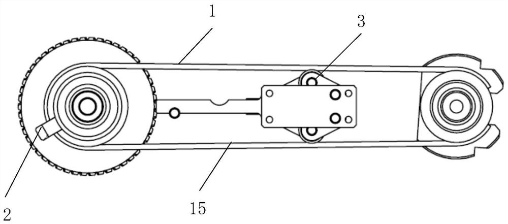
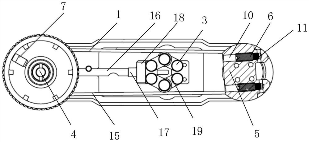
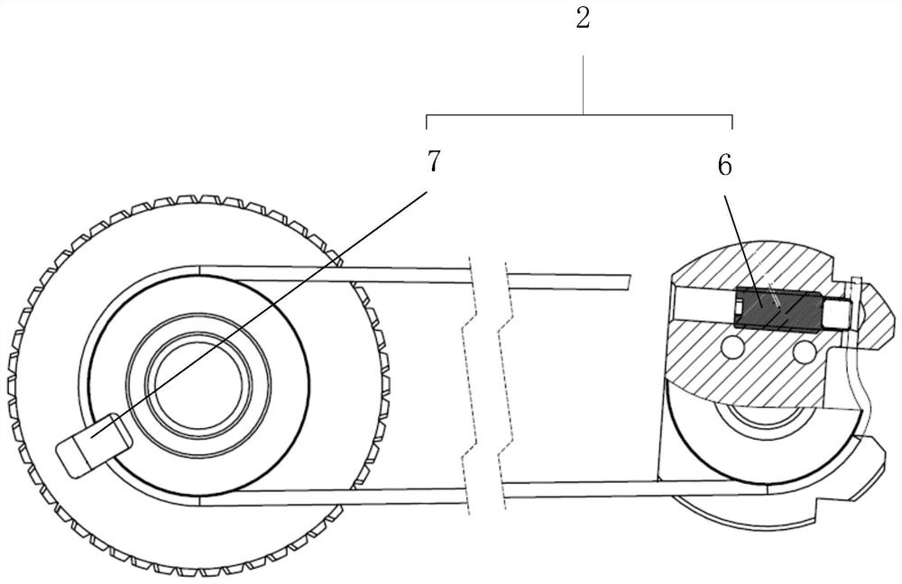
The invention provides a rope transmission mechanism. The rope transmission mechanism comprises a steel wire rope, a connecting device and a tensioning device, wherein the steel wire rope is sequentially wound on a driving wheel and a driven wheel in a certain direction and forms a steel wire ring; the driving wheel pulls the driven wheel to rotate through the steel wire rope; the connecting device comprises a driving wheel connecting device and driven wheel connecting devices; the driving wheel connecting device is arranged on the driving wheel and connects the driving wheel and the steel wire rope; the driven wheel connecting devices are arranged on the driven wheel and connect the driven wheel and the steel wire rope; and the tensioning device is arranged between the driving wheel and the driven wheel and connected with the steel wire rope and is used for tensioning the steel wire rope. According to the single-rope transmission in the embodiment of the invention, on the premise of a narrow installation space, the space utilization rate is increased, and the selected diameter of the rope is increased, so that the transmission rigidity is improved. The continuous tensioning mechanism is convenient to adjust, the upper section and the lower section of the steel wire rope are effectively and synchronously tensioned, and movement coordination and force transmission stability are guaranteed.

Description

technical field [0001] The invention relates to the technical field of a joint transmission mechanism of a multi-joint manipulator, in particular to a rope transmission mechanism and a rope transmission mechanism of a manipulator. Background technique [0002] Multi-degree-of-freedom humanoid robots are equipped with arms and dexterous hands with bionic joints. Unlike industrial manipulators, bionic dexterous hands have relatively sufficient space to design motion mechanisms. Due to the limitation of bionic hand shape and space structure, it is difficult for the current bionic dexterous hand to achieve precise control of fingers and sufficient gripping force. [0003] The existing similar schemes have the following problems: 1. The number of steel wire ropes is usually two, and the installation and maintenance are relatively complicated; 2. The rope end fixing structure and tensioning mechanism are complicated, and the size of the rope end locking parts is relatively large d...

Claims


Application Information

Patent Timeline
IPC IPC(8): B25J9/10
CPCB25J9/104
Inventor 邹风山何元一武桐刘世昌赵晨崔可夫
Owner SHENYANG SIASUN ROBOT & AUTOMATION
Why Eureka
Try Eureka