Eureka AIR delivers breakthrough ideas for toughest innovation challenges, trusted by R&D personnel around the world.

A system calibration method for a three-dimensional line-of-sight tracking system

A technology of eye tracking and system calibration, applied in the field of computer vision, can solve the problem that the light source and the screen are not within the field of view of the system camera, and achieve the effect of good calibration requirements, convenient operation and high calibration accuracy

Active Publication Date: 2021-10-15
UNIV OF SCI & TECH BEIJING
View PDF10 Cites 0 Cited by
  • Summary
  • Abstract
  • Description
  • Claims
  • Application Information

AI Technical Summary

Problems solved by technology

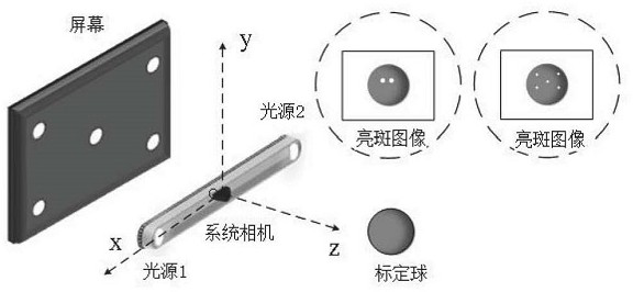
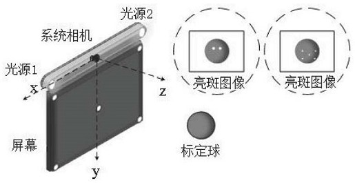
[0006] The purpose of the present invention is to provide a system calibration method for a three-dimensional line of sight tracking system, which is mainly used to calibrate the three-dimensional coordinates of the system light source in the camera coordinate system and the plane equation of the screen in the camera coordinate system, and can solve the problem that the light source and the screen are not in the same position. Problems within the field of view of the system camera, especially suitable for the near-eye line of sight tracking module, can better meet the calibration requirements of the 3D line of sight tracking system

Method used


Image

  • A system calibration method for a three-dimensional line-of-sight tracking system
  • A system calibration method for a three-dimensional line-of-sight tracking system
  • A system calibration method for a three-dimensional line-of-sight tracking system

Examples


Embodiment Construction

[0081] In order to make the objects, technical solutions, and advantages of the present invention, the embodiments of the present invention will be further described in detail below with reference to the accompanying drawings.

[0082] Embodiments of the present invention provide a system calibration method for a three-dimensional view line tracking system, such as figure 1 As shown, the method includes the following steps:

[0083] Calibrate the system camera to obtain internal parameters of the system camera, including focal length, like the main point, like the original size, distortion parameters, etc.

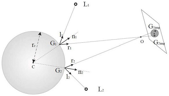
[0084] Place the calibration ball in the field of view of the system camera, shoot the shot image formed on the reflection on the ball and calibration ball;

[0085] Change the position of the laminated ball, shoot the calibration ball and shot image of multiple groups;

[0086] According to the spherical heart and shot coordinates of different positions, construct a plurality...


PUM


Abstract

The invention discloses a system calibration method for a three-dimensional line of sight tracking system. The method changes the position of the calibration sphere, photographs multiple groups of calibration spheres and bright spot images at different positions, and constructs multiple These planes intersect the line connecting the light source and the optical center of the system camera, thereby obtaining the straight line where the light source is located, setting multiple possible light source points on the straight line where the light source is located, and bringing them into the 3D line-of-sight tracking system for optimization Solve the problem, converge the possible light source points to the real light source point, obtain the three-dimensional space coordinates of the real light source, and calibrate the screen in the same way. The method of the invention fully considers the influence of various error factors, can solve the problem that the light source and the screen are not within the field of view of the system camera, and is especially suitable for the near-eye line of sight tracking system. It has the advantages of high calibration accuracy and convenient operation, and can better meet Calibration requirements for 3D gaze tracking system.

Description

Technical field [0001] The present invention relates to the field of computer visual technology, and in particular, to a system calibration method for a three-dimensional view line tracking system. Background technique [0002] Sight tracking techniques can be roughly divided into two categories: gaze estimation methods based on two-dimensional mapping and gaze estimation based on three-dimensional models. The two-dimensional staringal estimation system is typically composed of a camera and a light source, wherein the eye is attached (gaze point, POR) is estimated by the calibrated gaze mapping function determined by the user calibration. Two-dimensional staring tracking typically utilizes a second-order polynomial to represent a direct mapping of a flicker-pupil difference vector to a gaze point (POR), with most of the polynomial coefficients for user specific, need to be determined during user calibration, users need to stare A plurality of points on the screen calculate unknow...

Claims


Application Information

Patent Timeline
Patent Type & Authority Patents(China)
IPC IPC(8): G06T7/80
CPCG06T7/80
Inventor 迟健男杨作云陈秋月范硕孙杭程宇
Owner UNIV OF SCI & TECH BEIJING
Why Eureka
Eureka Blog
Learn More