Operation method of detachable mold trolley device for autoclaved aerated concrete block side plates

A concrete block and autoclaved aerated technology, which is applied in the direction of mold fixtures, molds, mold auxiliary parts, etc., can solve the problem that the autoclaved aerated concrete block is not easy to take out, which is unfavorable for the production and transportation of autoclaved aerated concrete blocks Difficult cutting lines and other problems, to achieve the effect of easy cutting operation, novel structure, and easy splicing

Pending Publication Date: 2021-07-02
河南新时代建材有限公司
View PDF5 Cites 0 Cited by
  • Summary
  • Abstract
  • Description
  • Claims
  • Application Information

AI Technical Summary

Problems solved by technology

[0004] In view of the above situation, in order to overcome the defects of the prior art, the present invention provides an operation method for the detachable formwork device of the autoclaved aerated concrete block side plate, which effectively solves the problem of the existing autoclaved aerated concrete block formwork. After the car is formed, it is not easy to take out the autoclaved aerated concrete block, and it is also difficult to transport to the cutting line, which is not conducive to the production of the autoclaved aerated concrete block

Method used


Image

  • Operation method of detachable mold trolley device for autoclaved aerated concrete block side plates
  • Operation method of detachable mold trolley device for autoclaved aerated concrete block side plates
  • Operation method of detachable mold trolley device for autoclaved aerated concrete block side plates

Examples


Embodiment Construction

[0018] Attached below Figure 1-3 The specific implementation manner of the present invention will be described in further detail.

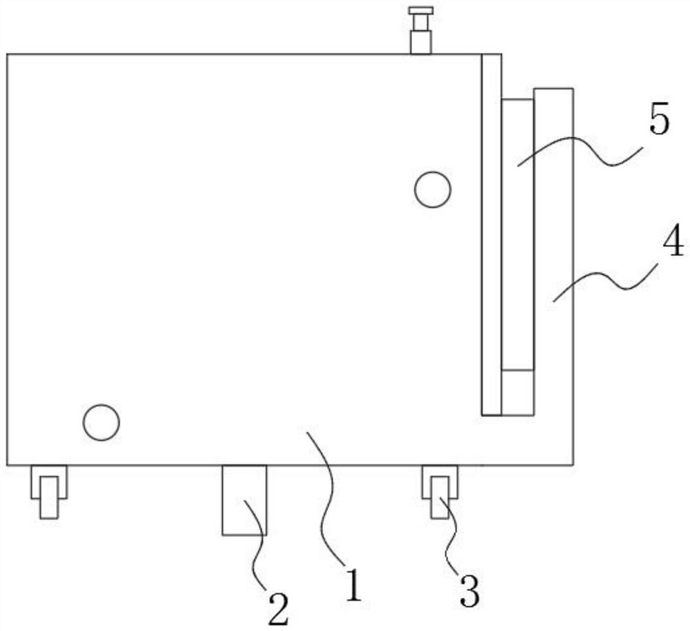
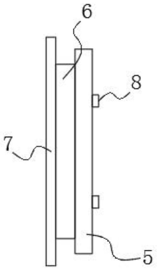
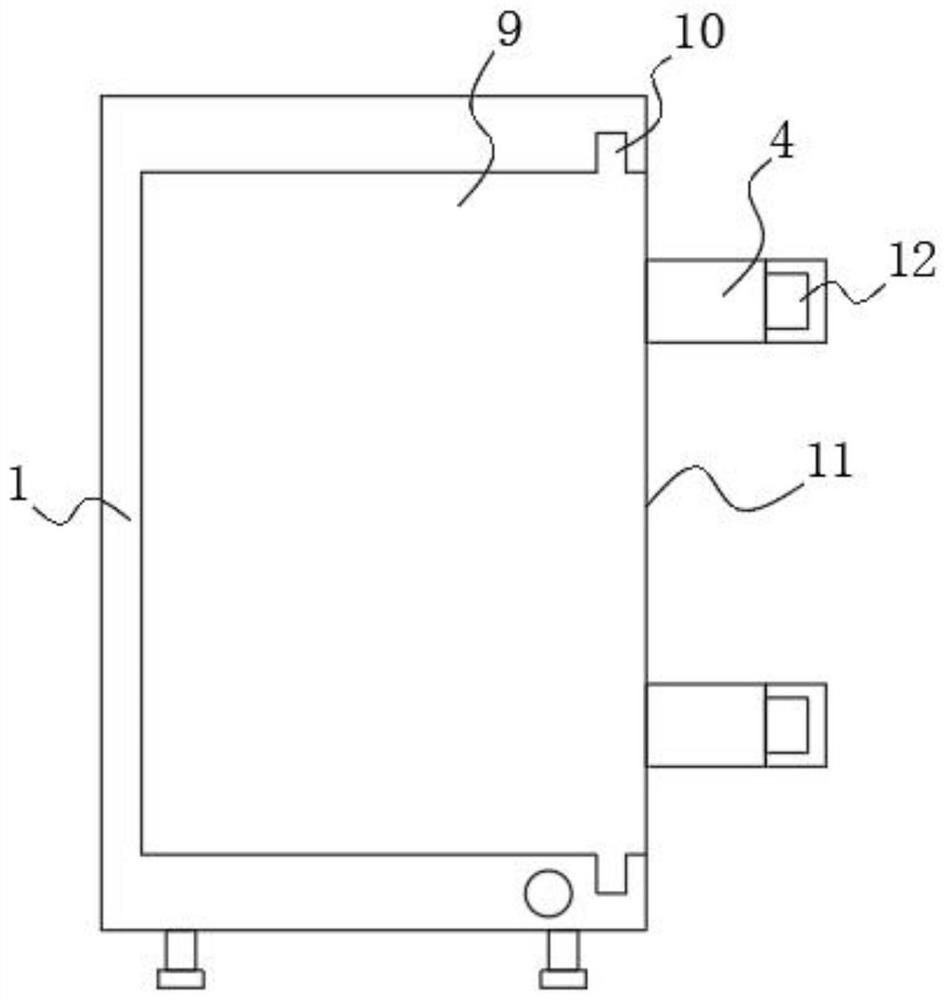
[0019] Example, by Figure 1-3 Given, the present invention provides a method for operating a detachable mold vehicle device for the side plate of an autoclaved aerated concrete block, including a bottom vehicle 1, a lower running line 2, a roller 3, a side guard frame 4, a side bottom vehicle 5, a transition Block 6, side baffle plate 7, limit block 8, inner cavity 9, card slot 10, side opening 11, limit groove 12, side running line 13 and connecting block 14, the middle part of the bottom end of the bottom car 1 is provided with a down running line 2. Several rollers 3 are installed at the bottom of the bottom car 1 close to both ends. Two side guards 4 are symmetrically welded on the bottom of one side of the bottom car 1. The inner side of the side guard 4 is provided with a side bottom car 5, and the side bottom One side of the car 5 is pr...


PUM


Abstract

The invention discloses an operation method of a detachable mold trolley device for autoclaved aerated concrete block side plates, and solves the problems that after an existing mold trolley for autoclaved aerated concrete blocks is formed, autoclaved aerated concrete blocks are difficult to take out, meanwhile, the autoclaved aerated concrete blocks are difficult to transport to a cutting line, and the production of the autoclaved aerated concrete blocks is not facilitated. The device comprises a bottom trolley, a lower walking line, rollers, side walking lines and connecting blocks; the lower walking line is arranged in the middle of the bottom end of the bottom trolley; the rollers are installed at the positions, close to the two ends, of the bottom of the bottom trolley; two side protection frames are symmetrically welded to the bottom of one side of the bottom trolley; side bottom trolleys are arranged on the inner sides of the side protection frames; transition blocks are arranged on one sides of the side bottom trolleys; side baffles are arranged at one ends of the transition blocks; and a plurality of limiting blocks are arranged on the other sides of the side bottom trolleys. According to the device, the structure is novel, the concept is ingenious, the mold trolley is convenient to splice and use, separation after forming is convenient, cutting operation of formed cuboid autoclaved aerated concrete blocks is convenient, and production is facilitated.

Description

technical field [0001] The invention relates to a mold car device, in particular to an operation method of a detachable mold car device for an autoclaved aerated concrete block side plate. Background technique [0002] Autoclaved aerated concrete blocks are made of fly ash, lime, cement, gypsum, slag, etc. A porous concrete product made by steam curing and other processes. [0003] During the production of autoclaved aerated concrete blocks, the materials need to be poured into the mold car, and after drying to form a rectangular autoclaved aerated concrete block, the autoclaved aerated concrete block is taken out from the mold car and transported to the cutting line After the existing autoclaved aerated concrete block mold car is formed, it is not easy to take out the autoclaved aerated concrete block, and it is also difficult to transport the autoclaved aerated concrete block to the cutting line, which is not conducive to the autoclaved aerated concrete block block produ...

Claims


Application Information

Patent Timeline
Patent Type & Authority Applications(China)
IPC IPC(8): B28B7/00
CPCB28B7/0041B28B7/0002B28B7/0014
Inventor 王治国乔军委张卫强李刚
Owner 河南新时代建材有限公司
Why Eureka
Try Eureka