Domestic sewage treatment equipment with biological fluidized bed and biological aerated filter

A biological aerated filter and domestic sewage technology, applied in the field of sewage treatment, can solve the problems of inconvenient installation and maintenance, large floor area, etc.

Pending Publication Date: 2021-07-02
江西益洁环保技术有限公司
0 Cites 0 Cited by

AI-Extracted Technical Summary

Problems solved by technology

[0004] The purpose of the present invention is to provide a biological fluidized bed aerated biological filter domestic sewage treatment ...

Method used

Above-mentioned biological fluidized bed aerated biofilter domestic sewage treatment equipment, by domestic sewage treatment equipment is divided into single functional area, when using, these single functional areas are combined together again, make domestic sewage treatment equipment transport convenient , It is easy to install, and at the same time, it reduces the infrastructure occupation of the infrastructure, and reduces the occupation area.
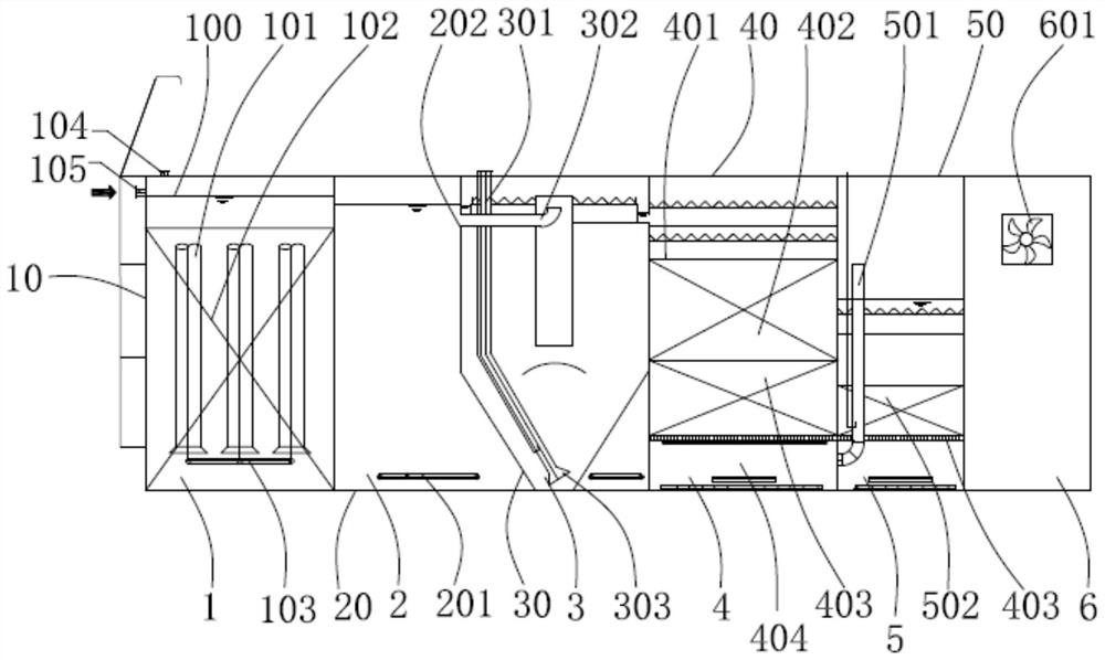
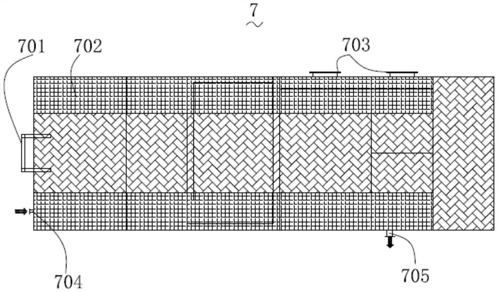
Concrete, in the present embodiment, the side that described clean water district 7 communicates with sand filter district 5 is provided with described backwash water inlet (figure is not marked), the other side of described clean water district 7 A main water outlet 705 is provided to discharge filtered clean water. An inspection staircase 701 is provided on one side of the clean water area 7 to detect the upper end of the clean water area 7. A glass grille cover plate 702 is arranged on the upper end of the clean water area 7. A discharge port 703 is provided on the side, and a general water inlet 704 communicating with the sand filter area 5 is also provided so that the water in the sand filter area 5 enters the clean water area 7 . The domestic sewage treated in the sewage tank enters the biological fluidized bed contact oxidation zone 1 by gravity from the main water inlet 704. The biological fluidized bed contact oxidation zone 1 is equipped with three fluidized beds 101, biological spherical packing 102, and a perforated aeration system 103. The sewage enters the hydrolytic acidification zone 2 from the bottom of the biological fluidized bed contact oxidation zone 1, and the hydrolytic acidification zone 2 is equipped with an intermittent stirring device 201 to prevent the deposition of activated sludge.
During reactor operation, domestic sewage enters biological fluidized bed contact oxidation zone 1 by total water inlet 704, adopts the fluidized bed process that biological spherical filler 102, three fluidized bed 101, perforated aeration system 103 combine, To form a highly specific active biofilm, multiple reaction sections can be arranged sequentially along the direction of water flow to meet various treatment objectives for carbonization, nitrification, pre- or post-denitrification reactions. It can effectively reduce organic matter, ammonia nitrogen, total phosphorus and total nitrogen in biochemical sewage. The effluent flows into the hydrolytic acidification tank 2 by itself, and intermittent stirring is used to avoid the deposition of activated sludge in the hydrolytic acidification tank. The inverted A/O process does not need to reflow the digestive liquid, which e...

Abstract

The invention provides domestic sewage treatment equipment with a biological fluidized bed and a biological aerated filter. The domestic sewage treatment equipment comprises a biological fluid bed contact oxidation area, a hydrolytic acidification area, a central flow guide type settling area, a biological fluid bed aeration filter area, a sand filter area, a clear water area and an equipment room which are arranged in sequence. Water flows through the hydrolytic acidification area, the central flow guide type settling area, the biological flow bed aeration filtering area, the sand filter area and the clear water area from the biological flow bed contact oxidation area and then is discharged; the hydrolytic acidification area is communicated with the outer side space of the central flow guide type settling area; and the equipment room is located at the tail of the whole sewage treatment equipment. According to the domestic sewage treatment equipment with the biological fluidized bed and the biological aerated filter, the domestic sewage treatment equipment is divided into the single functional areas, and when the domestic sewage treatment equipment is used, the single functional areas are combined together, so that the domestic sewage treatment equipment is convenient to transport and mount, and meanwhile, the infrastructure land occupation of infrastructure is reduced; and the occupied area is reduced.

Application Domain

Treatment with aerobic and anaerobic processes

Technology Topic

Sand filterBiological fluid +7

Image

  • Domestic sewage treatment equipment with biological fluidized bed and biological aerated filter
  • Domestic sewage treatment equipment with biological fluidized bed and biological aerated filter
  • Domestic sewage treatment equipment with biological fluidized bed and biological aerated filter

Examples

  • Experimental program(1)

Example Embodiment

[0021] In order to facilitate understanding of the present invention, the present invention will be described more fully described with reference to the related drawings. Several embodiments of the present invention are given in the drawings. However, the present invention can be implemented in many different forms, and is not limited to the embodiments described herein. Conversely, the purpose of providing these examples is to make the disclosure of the present invention more thoroughly.
[0022] It should be noted that when the element is referred to as "fixed to" another element, it can be directly in another element or may also exist in the middle. When a component is considered to be "connected" another element, it may be directly connected to another element or may always exist in the center element. The terms "vertical", "horizontal", "left", "right", and similar expressions are merely for illustrative purposes only.
[0023] All techniques and scientific terms used herein are identical to those skilled in the art, unless otherwise defined. The terms used herein in the specification of the present invention are intended to describe specific embodiments, and is not intended to limit the invention. The terms "and / or" as used herein include any and all combinations of one or more related list items.
[0024] The present invention provides a biofilm treatment apparatus, including a biofluidic bed contact oxidation zone 1, hydrolyzed acidification zone 2, a bio-fluid-fluidized sedimentation zone 3, bio-flow bed aeration filtering District 4, sand filter region 5, water region 7, and equipment 6, water flow from the biosaidal bed contact oxidation zone 1 through the hydrolyte acid region 2, the center flow-through precipitation zone 3, the biological flow Bed Aeratory Filter Zone 4, the sand filter region 5, the water release zone 2 is in the outer space in which the hydrolyzate zone 2 is in the outer space of the center flow-through precipitation zone, and the device is located throughout the sewage treatment equipment. The tail.
[0025] The above biosensive bed aeration biological filter life sewage treatment equipment, by dividing the sewage treatment equipment into a single functional area, then combined with these single functional areas, making it easy for domestic sewage treatment equipment to facilitate installation At the same time, it reduces the foundation coverage of the foundation, which reduces the area of ​​coverage.
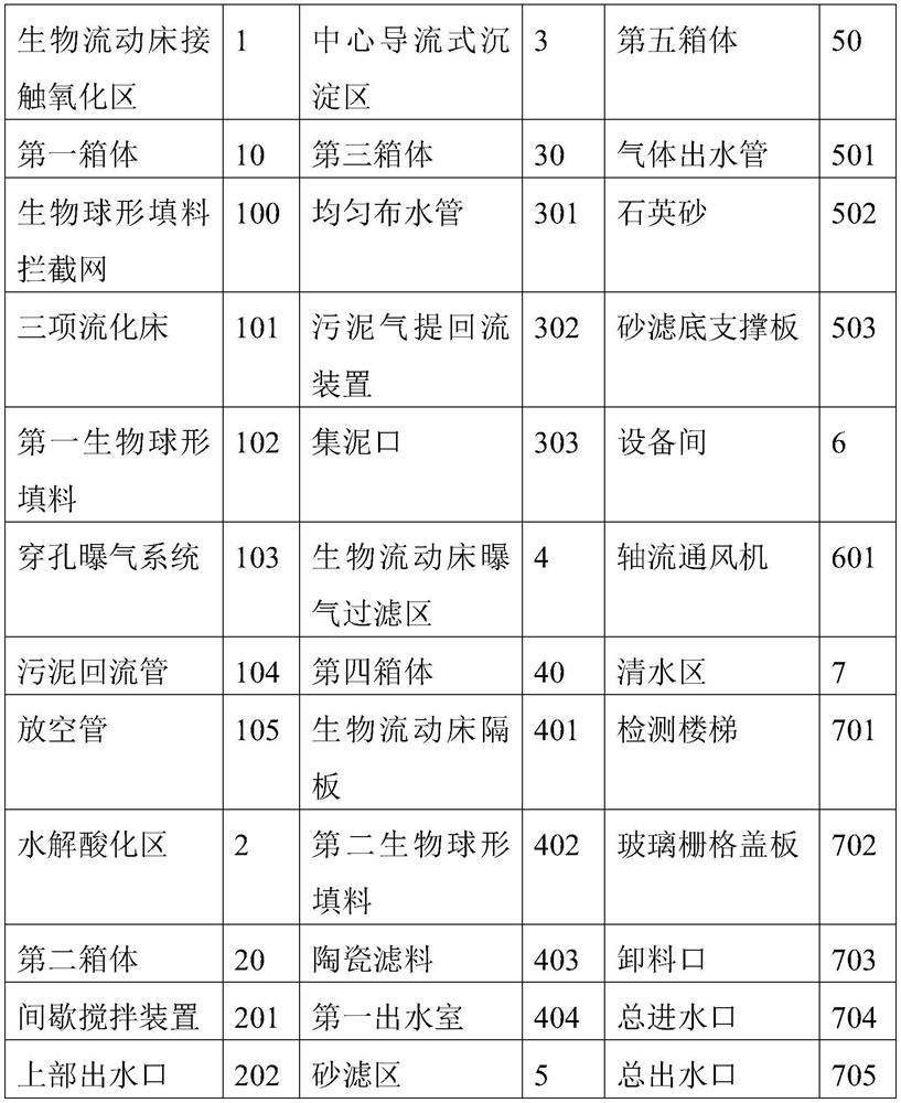
[0026] Specifically, in the present embodiment, the biosensive bed contact oxidation zone includes a first box body 10, a biological spherical filler intercepting net 100 in the first box 10, a first biological spherical filler 102, three The entries, the perforated aeration system 103, which is provided at the sludge return tube 104 of the first box body 10, and venting the tube 105; the first box body 10 is provided with a bottom water outlet (Figure Summary), the bottom water port is in communication with the water-necked area 2, and the aeration pipe of the perforated aeration system 103 is connected to the perforated aeration system 103 of the bottom portion by the top grid cover.
[0027] Specifically, in the present embodiment, the water-correction area 2 includes a second box body 20 and a batch stirring device 201, and the upper portion of the second box body 20 is provided with an upper water port 202, the upper outlet 202 Connect to the center flow-through precipitation zone 30.
[0028] Specifically, in the present embodiment, the central flow-flow precipitation zone 3 includes a third box body 30 and an overwater tube disposed within the third box 30 (not marked), and the center guide ( The picture is not marked), the sludge gas reflow device 302, the sludge collection port (not marked), the mud (not marked), the peripheral overflow coin (the figure is not marked), uniform cloth water pipe 301 The lower end of the uniform cloth 301 is provided with a colored port 303, which extends from the top plate of the third box 30 inwardly in communication with the sludge return tube 104. The sewage is entered from the upper portion of the center guide tube, and after the central guidance tube is uniformly distributed, it is uniformly distributed on the cross section of the third box body 30 after the reflection plate at the bottom of the center guide barrel. The third box body 30 The outlet of the 30 is disposed on the surrounding overflow coil and communicates with the biological flow aeration filter region 4.
[0029] Sewage from the upper portion of the hydrolysis acidification zone 2 passes through the pipe into the center flowing precipitation zone 3, the sludge produced in the center flow-through precipitation region 3 passes the sludge gas reflow reflux 302 to reflow the sludge gas reflow device 302 To the biosensive bed contact oxidation zone 1 or gas refers to the septic tank, periodically.
[0030] Specifically, in the present embodiment, the biosensive bed aeration filter region includes a fourth box body 40 and an in-water shred plate disposed within the fourth box body 40, which is not marked. The bed partition 401, the second bio-spherical filler 402, the ceramic filter material 403, the filter bottom support plate (not shown), the anti-rinse drain and absorbing overflow coil (not marked) and the first outlet chamber 404, the The fourth box body 40 is provided with a drain opening corresponding to the first outlet chamber 404.
[0031] Specifically, in the present embodiment, the first outlet chamber 404 includes a microporous aeration system (not shown), the water system (not marked), the first anti-rinsing wastewater system (not shown) ), The first reverse washing barrier system (not shown), the water supply system (Fig. [Fig. [Figure not marked) is a gas pipeline, the effluent system being connected to the sand filter region 5.
[0032] Specifically, in the present embodiment, the sand filter region 5 includes a fifth box body 50 and a sand filter layer disposed within the fifth box 50 (not marked), a sand filter floor support plate 503. The second extension chamber (not shown), the second outlet chamber (not shown) mainly includes a second anti-rinsing wastewater system (not shown), the second anti-rinsing cloth system (Figure Summit), the water pipe (not marked), the water line is connected to the water region 7. The sand filter layer of the sand filter includes a quartz sand 502, and a gas delivery pipe 501 connected to the first outlet chamber 404. Among them, the sewage separated from the center-flowing sedimentation zone 3 mud water into the bioflower bed aeration filter region 4, and the sewage is sequentially passed through the biological spherical filler 402, ceramic filter 403, water by the biosained bed partition 401. The chamber 404, from the outlet chamber 404, passes into the sand filter 501 through gas proposing water pipe 501. The sewage passes through the upper inlet of the sand filter region 5 through the quartz sand 502, and the water pipe is passed through the water pipe 7 through the water pipe 5, and finally the total outlet 705 is discharged.
[0033]Specifically, in the present embodiment, the water regions 7 are provided on one side in which the sand filter region 5 is inserted with the revershed washed water (not shown), and the other side of the water regions 7 has a total The water exit 705 is provided with a clear water that is filtered, and the water sector 701 is provided on the water area 701 in order to detect the upper end of the water region 7, and the upper end of the water region 7 is provided with a glass grid cover 702, and the upper side of the water region 7 is provided. The unloading port 703 is also provided with a total advanced moisture port 704 communicating with the sand filter region 5 such that the water of the sand filter zone 5 into the water region 7. Domestic sewage after the treatment of the sewage pool is from the total water supply port 704 from the biosensive bed contact oxidation zone 1, and three fluidized bed 101, biological spherical filler 102, perforated aeration system 103, in the biosair flow contact oxidation zone 1. The sewage enters the hydrolyzate zone 2 from the bottom of the biosair flow contact oxidation zone 1, and the hydrolyzed acidified zone 2 is provided with an intermittent mixing apparatus 201, and the active sludge can be prevented.
[0034] Specifically, in the present embodiment, the device 6 includes an electronically controlled system (not marked), aeration system (not marked), the anti-flush system (not shown), air exhaust system ( The picture is not marked). Electronic control system is used to control the mechanical equipment of the entire integrated device; the aeration system and the perforation aeration system 103 of the bioflower bed contact the oxidation zone 1, the hydrolyzed acidified zone 2 intermittent mixture, the center flow-through precipitation zone 3 The sludge gas reflow device 302, the microporous aeration system of the biofilm bed aeration filter region 4, the backwashing cloth system, the water absorbing system, the anti-rushing gas system connection of the sand filter region 5; the anti-rinse system The inlet end is connected to the water region 7, the water-absorbent wrapping system of the anti-flushing system and the anti-flushing wastewater system and the sand filter system of the biofilm bed aerated filter area 4 are connected in parallel; the air exhaust system is sidedly discharged.
[0035] Specifically, in the present embodiment, the inter-device 6 air exhaust system includes an axial flow fan 601. The upper surface of the apparatus is produced by steel or glass steel, and the excessive gas produced by carbon dioxide and air generated during process reaction can be produced, and the internal pressure is too large. At the same time, it can greatly meet the needs of different conditions.
[0036] When the reactor is operated, the sewage of life is from the total water supply port 704 into the biosensive bed contact oxidation zone 1, and the fluidized bed process combined with the bio-spherical filler 102, the three fluidized bed 101, the perforated aeration system 103, forming a height special Sexual active biofilm, multiple reaction segments can be arranged in the direction of water flow to meet a variety of treatment targets for carbonization, nitrification, pre-or rear denitrification reaction. It can effectively reduce organics, ammonia nitrogen, total phosphorus, total nitrogen in biochemical sewage. Self-flowing water into the hydrolyzate tank 2, avoiding hydrolyzed acidized pool of active sludge deposition by intermittent agitation, using an inverted A / O process without digestive liquid generation, effectively solving the problem of insufficient carbon source when the hydrolyzed tank is used. Self-flowing from the center of the water flow, after the uniform cloth of the water pipe and the center guide, the mud water separation is performed, and the sludge is refluxed to the biosained bed contact oxidation zone 1 supplement sludge. Phosphorus is accurate, the other part is refluxed to the septic tank periodically cleaned; the supernatant passes through the overflow stream into the biosensive bed aeration filter zone 4, the biological flow bed aeration filter area 4 uses biological spherical filler 402 and ceramic filter 403 In combination, the biosensive bed aerated filter area can form a highly specific active biofilm, which can improve the processing efficiency of the unit volume of the biofilm bed aeration filter area, and increase process stability, thereby reducing biosensive bed aeration. The volume of the filter area 4; the water system is provided with a tattoo circuit 501 to effectively solve the problem of elevated water levels due to the reduction in filtering velocity during operation. Bioflow Bed Aeration Filter Zone 4 can further reduce organics, ammonia nitrogen, total phosphorus, total nitrogen in biochemical sewage. Self-flow in the water into the sand filter 5, further removing SS (suspended matter), organic matter, total phosphorus in wastewater through the effect of the quartz sand 502. Outlet enters the water regions 7, and the water flow area 7 is mainly provided to provide anti-polishing water for the biosaidal bed aerated filter region 4 and the sand filter region 5. The total drainage 705 of the Water Water is reached in the "urban sewage treatment plant pollutant emission standard" GB18918-2002 level A emission standard emissions.

PUM

no PUM

Description & Claims & Application Information

We can also present the details of the Description, Claims and Application information to help users get a comprehensive understanding of the technical details of the patent, such as background art, summary of invention, brief description of drawings, description of embodiments, and other original content. On the other hand, users can also determine the specific scope of protection of the technology through the list of claims; as well as understand the changes in the life cycle of the technology with the presentation of the patent timeline. Login to view more.
Why Eureka
Try Eureka