Tubular column for separated layer water injection

A layered water injection and pipe string technology, which is applied in the direction of production fluid, wellbore/well components, earthwork drilling and production, etc., can solve the problems of small backwash channel, heavy workload, low injection precision, etc., and achieve fast installation and operation Convenience, improvement of development efficiency, and advanced structure

Inactive Publication Date: 2016-04-20
李永立
View PDF9 Cites 28 Cited by
  • Summary
  • Abstract
  • Description
  • Claims
  • Application Information

AI Technical Summary

Problems solved by technology

[0003] ①The display of the underground layering effect is not intuitive enough, and a professional instrument needs to be installed for testing;
[0004] ②The backwashing channel is small, which cannot meet the requirements of large displacement well washing;
[0005] ③The adjustment of the water volume of the water distribution device is realized by replacing the water distribution core, which requires repeated throwing and fishing, the workload is heavy, and the distribution accuracy is low;
[0006] ④Lack of a reliable downhole safety control system, unable to meet the current offshore safety and environmental protection requirements

Method used


Image

  • Tubular column for separated layer water injection
  • Tubular column for separated layer water injection
  • Tubular column for separated layer water injection

Examples


Embodiment Construction

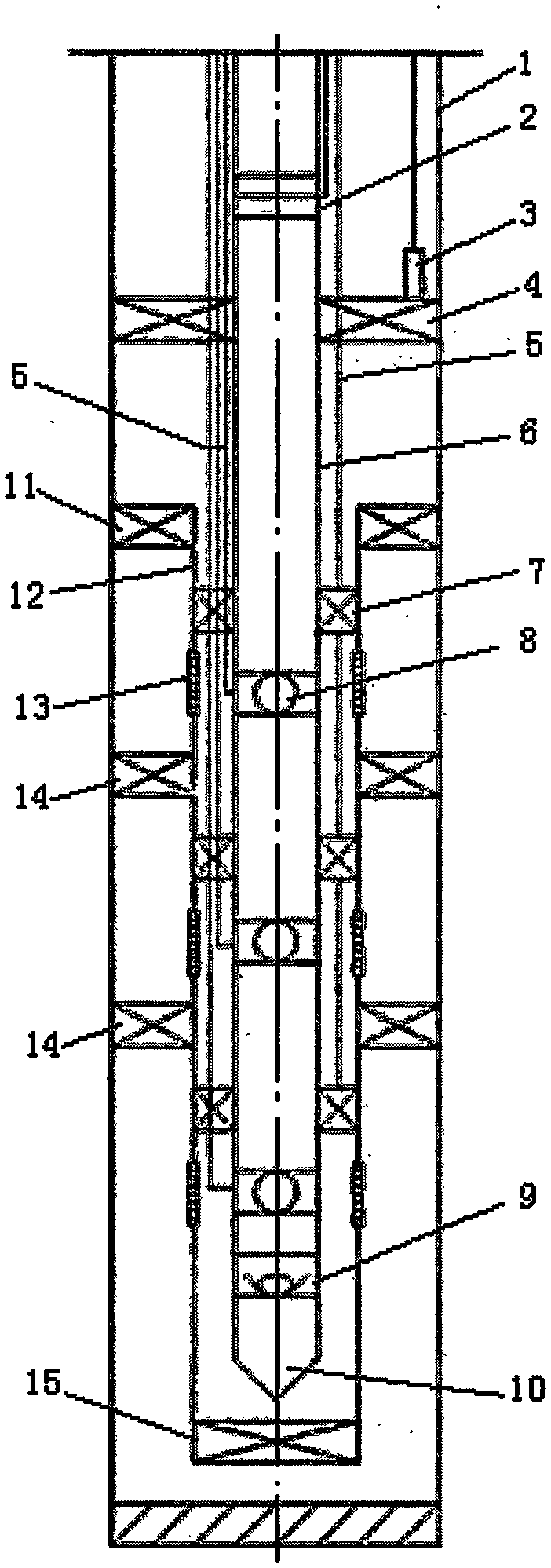
[0020] refer to Figure 1-Figure 5 , a layered water injection string, including a casing 1, a downhole safety valve 2, an exhaust valve 3, a multi-tubular through-type packer 4, a hydraulic control pipeline 5, a tubing 6, a hydraulic control packer 7, a slide Sleeve nozzle 8, backwash valve 9, guide joint 10, suspension packer 11, sand control casing 12, sand filter pipe 13, interlayer packer 14 and wire plug 15. The tubing 6 is sequentially connected with the downhole safety valve 2, the multi-tubular through-type packer 4, the hydraulic control packer 7, the sliding sleeve nozzle 8, the hydraulic control packer 7, the sliding sleeve nozzle 8, the hydraulic control seal Spacer 7, sliding sleeve water nozzle 8, backwash valve 9, guide joint 10, sand control casing 12 is installed and connected to oil pipe 6, and suspension packer 11 and sand filter pipe are installed and connected to sand control casing 12 in sequence 13. Interlayer packer 14, filter sand pipe 13, interlayer...


PUM


Abstract

A tubular column for separated layer water injection comprises a subsurface safety valve, an exhaust valve, a multi-tube traverse packer, a hydraulic-control pipeline, hydraulic-control packers, sliding sleeve type water nozzles, a backwashing valve, a suspension packer, a sand-prevention bushing, sand filtering tubes and interlayer packers. An oil tube is sequentially connected with the subsurface safety valve, the multi-tube traverse packer, the corresponding hydraulic-control packer, the corresponding sliding sleeve type water nozzle, the corresponding hydraulic-control packer, the corresponding sliding sleeve type water nozzle, the corresponding hydraulic-control packer, the corresponding sliding sleeve type water nozzle, the backwashing valve and a guide connector. The sand-prevention bushing is installed outside the oil tube in a connected mode. The suspension packer, the corresponding sand filtering tube, the corresponding interlayer packer, the corresponding sand filtering tube, the corresponding interlayer packer, the corresponding sand filtering tube and a plug are sequentially installed on the sand-prevention bushing in a connected mode, and a bushing is arranged on the outmost part. The exhaust valve is installed on the multi-tube traverse packer in a connected mode, the hydraulic-control pipeline is installed on the exhaust valve for control, the hydraulic-control packers are traversed, connected and controlled through the same hydraulic-control pipeline, the sliding sleeve type water nozzles are connected through the hydraulic-control pipeline for control, and the subsurface safety valve is connected with the hydraulic-control pipeline for control.

Description

technical field [0001] The invention relates to a water injection string, in particular to a layered water injection string. Background technique [0002] The structure of the existing layered water injection string is generally a Y341 compression packer combined with a hollow water distributor. The layered water injection string with this structure has played a role in the layered water injection process, but it also has the following problems Disadvantages or deficiencies: [0003] ①The display of the underground layering effect is not intuitive enough, and a professional instrument needs to be installed for testing; [0004] ②The backwashing channel is small, which cannot meet the requirements of large displacement well washing; [0005] ③The adjustment of the water volume of the water distribution device is realized by replacing the water distribution core, which requires repeated throwing and fishing, the workload is heavy, and the distribution accuracy is low; [00...

Claims


Application Information

Patent Timeline
Patent Type & Authority Applications(China)
IPC IPC(8): E21B43/20
CPCE21B43/20
Inventor 李永立
Owner 李永立
Why Eureka
Try Eureka