
Tracking method and device for radar and photoelectric linkage

A photoelectric and radar technology, applied in the computer field, can solve the problems of long image time interval, slow radar rotation speed, long time interval, etc., and achieve the effect of continuous tracking

Active Publication Date: 2021-11-19
北京高普乐光电科技股份公司
View PDF7 Cites 0 Cited by
  • Summary
  • Abstract
  • Description
  • Claims
  • Application Information

AI Technical Summary

Problems solved by technology

[0003] However, due to the slow rotation speed of the radar and the long time interval of the echo signal between the radar and the target object
Therefore, the time interval for the radar to obtain the position information of the target object is also longer, and correspondingly, the time interval for the control device to determine the PTZ value of the photoelectric turntable is also longer, and then the time interval between the images containing the target object collected by the photoelectric pan / tilt The time interval is also long, which makes the photoelectric gimbal unable to continuously track the target object

Method used


Image

  • Tracking method and device for radar and photoelectric linkage
  • Tracking method and device for radar and photoelectric linkage
  • Tracking method and device for radar and photoelectric linkage

Examples


Embodiment Construction

[0044] In order to make the purpose, technical solution and advantages of the present application clearer, the present application will be further described in detail below in conjunction with the accompanying drawings and embodiments. It should be understood that the specific embodiments described here are only used to explain the present application, and are not intended to limit the present application.

[0045] An embodiment of the present application provides a radar and photoelectric linkage tracking method, which can be applied to a radar and photoelectric linkage early warning system. Specifically, the method can be applied to the photoelectric pan-tilt in the early warning system of radar and photoelectric linkage. Such as figure 1As shown, the early warning system includes a radar 110 , a photoelectric pan / tilt 120 and a control device 130 . Among them, the radar 110 is used for sending the first position information corresponding to the target object to the contro...


PUM


Abstract

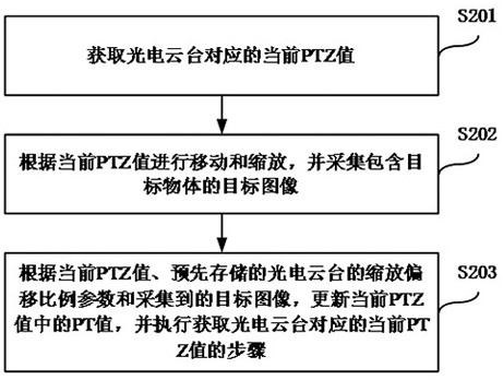
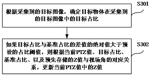
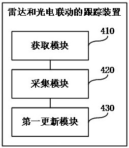
The present application relates to a tracking method and device for radar and photoelectric linkage. The method is applied to the photoelectric pan-tilt in the tracking system of radar and photoelectric linkage, and the method includes: obtaining the current PTZ value of translation, tilt and zoom corresponding to the photoelectric pan-tilt; moving and zooming according to the current PTZ value, and Acquiring a target image containing a target object; updating the translation and tilt PT value in the current PTZ value according to the current PTZ value, the pre-stored zoom offset ratio parameter of the photoelectric pan / tilt and the captured target image, and Execute the step of acquiring the current PTZ value corresponding to the photoelectric pan / tilt. The application can ensure that the photoelectric pan / tilt can continuously track the target object.

Description

technical field [0001] The present application relates to the field of computer technology, in particular to a radar and photoelectric linkage tracking method and device. Background technique [0002] At present, in common tracking systems, radar-linked photoelectric pan-tilts are usually used to track the target objects monitored in the monitoring area. During the tracking process, the radar can obtain the location information of the target object in real time (such as distance, direction, etc.), and send the location information of the target object to the control device. The control device determines the PTZ (Pan / Tilt / Zoom, translation / tilt / zoom) value corresponding to the photoelectric pan / tilt according to the position information of the target object and the photoelectric pan / tilt, and sends the PTZ value to the photoelectric pan / tilt . Afterwards, the photoelectric pan / tilt can move and zoom according to the PTZ value, and collect images containing the target object...

Claims


Application Information

Patent Timeline
Patent Type & Authority Patents(China)
IPC IPC(8): G01S13/86G01S13/66H04N5/232G06T7/292G06K9/00G06T7/70
CPCG01S13/86G01S13/66G06T7/292G06T7/70G06V20/40G06V20/44H04N23/69
Inventor 麻文斌郑维彦
Owner 北京高普乐光电科技股份公司
Learn More