Method and system for multi-frequency beamforming

A beamforming method and beamforming technology, applied in the field of array antenna design, can solve problems such as low forming efficiency and difficult forming, and achieve the effects of improving forming efficiency, reducing forming difficulty, and wide bandwidth

Active Publication Date: 2022-07-01
CHINA ELECTRONIC TECH GRP CORP NO 38 RES INST
View PDF6 Cites 0 Cited by
  • Summary
  • Abstract
  • Description
  • Claims
  • Application Information

AI Technical Summary

Problems solved by technology

[0006] The technical problem to be solved by the present invention is that the existing beamforming method has the problems of difficult beamforming and low beamforming efficiency when it is applied at multiple frequency points

Method used


Image

  • Method and system for multi-frequency beamforming
  • Method and system for multi-frequency beamforming
  • Method and system for multi-frequency beamforming

Examples


Embodiment 1

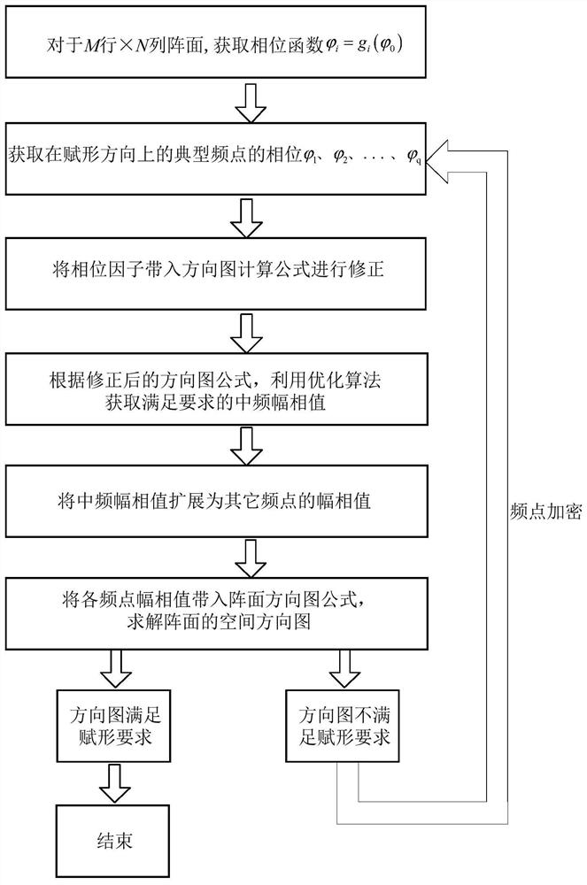
[0065] like figure 1 As shown, a multi-frequency beamforming method, the method includes:

[0066] Step 1: Obtain the phase function of the antenna front to be shaped;

[0067] Step 2: Obtain the phase of the typical frequency point in the shaping direction;

[0068] Step 3: Substitute each phase into the one-dimensional linear array pattern calculation formula for correction, and obtain the corrected pattern formula;

[0069] Step 4: According to the revised pattern formula, use the optimization algorithm to obtain the intermediate frequency amplitude and phase value that meets the requirements;

[0070] Step 5: Extend the IF amplitude and phase values ​​to the amplitude and phase values ​​of other frequency points;

[0071] Step 6: Substitute the amplitude and phase values ​​of each frequency point into the two-dimensional array pattern formula to solve the spatial pattern of the front, that is, the beamforming pattern;

[0072] Step 7: Determine whether the beamforming ...

Embodiment 2

[0110] Corresponding to Embodiment 1 of the present invention, Embodiment 2 of the present invention further provides a multi-frequency beamforming system, where the system includes:

[0111] The phase function acquisition module is used to acquire the phase function of the antenna array to be shaped;

[0112] The phase acquisition module is used to acquire the phase of the typical frequency point in the shaping direction;

[0113] The pattern correction module is used to substitute each phase into the one-dimensional linear array pattern calculation formula for correction, and obtain the corrected pattern formula;

[0114] The intermediate frequency amplitude and phase value acquisition module is used to obtain the intermediate frequency amplitude and phase value that meets the requirements by using the optimization algorithm according to the revised pattern formula;

[0115] The amplitude and phase expansion module is used to expand the amplitude and phase value of the inte...


PUM


Abstract

The invention discloses a multi-frequency point beam forming method and system. The method includes: acquiring the phase function of the antenna array to be shaped; acquiring the phase of typical frequency points in the shaping direction; and substituting each phase into a Modify the calculation formula of the dimensional linear array pattern to obtain the revised pattern formula; according to the revised pattern formula, use the optimization algorithm to obtain the intermediate frequency amplitude and phase value that meets the requirements; expand the intermediate frequency amplitude and phase value to the amplitude of other frequency points. Phase value; Substitute the amplitude and phase values ​​of each frequency point into the two-dimensional array pattern formula to solve the spatial pattern of the front, that is, the beamforming pattern; judge whether the beamforming pattern meets the forming requirements, if not , the frequency points are encrypted, and the above steps are repeated until the obtained beamforming pattern meets the forming requirements; the present invention has the advantages that the forming is easier and the forming efficiency is high.

Description

technical field [0001] The invention relates to the field of array antenna design, and more particularly to a multi-frequency beam forming method and system. Background technique [0002] Array antennas are widely used in radar, electronic warfare and other fields. In many cases, radar, electronic warfare, etc. require special-shaped antenna beams, such as cosecant square forming, beam broadening, flat-top beam, etc. Beam forming is an important part of phased array antenna design. [0003] At present, most of the shaping methods are optimized for a single frequency point. When the shaping direction adopts the power divider synthesis or the antenna broadband operation, if only the intermediate frequency is shaped, due to the existence of the dispersion effect, the phases of other frequency points will be generated. A certain offset, when the bandwidth is wider, the offset is larger, which leads to the deterioration of the pattern and cannot meet the shaping requirements. ...

Claims


Application Information

Patent Timeline
Patent Type & Authority Patents(China)
IPC IPC(8): H04B7/06
CPCH04B7/0617
Inventor 郑灵曹军李晓孟程圣华周围丁文兵强云飞
Owner CHINA ELECTRONIC TECH GRP CORP NO 38 RES INST
Why Eureka
Try Eureka