Children's bed with anti-collision device
An anti-collision and crib technology, which is applied in the direction of rocking beds, children's furniture, household appliances, etc., can solve problems such as damage to the bed body, affecting children's sleep, and increasing the activity space of the bed body
- Summary
- Abstract
- Description
- Claims
- Application Information
AI Technical Summary
Problems solved by technology
Method used
Image
Examples
Embodiment 1
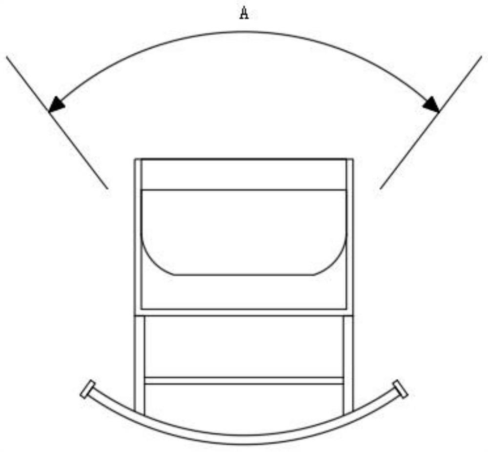
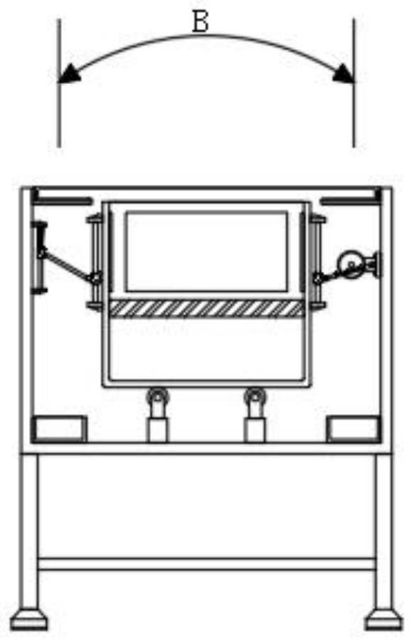
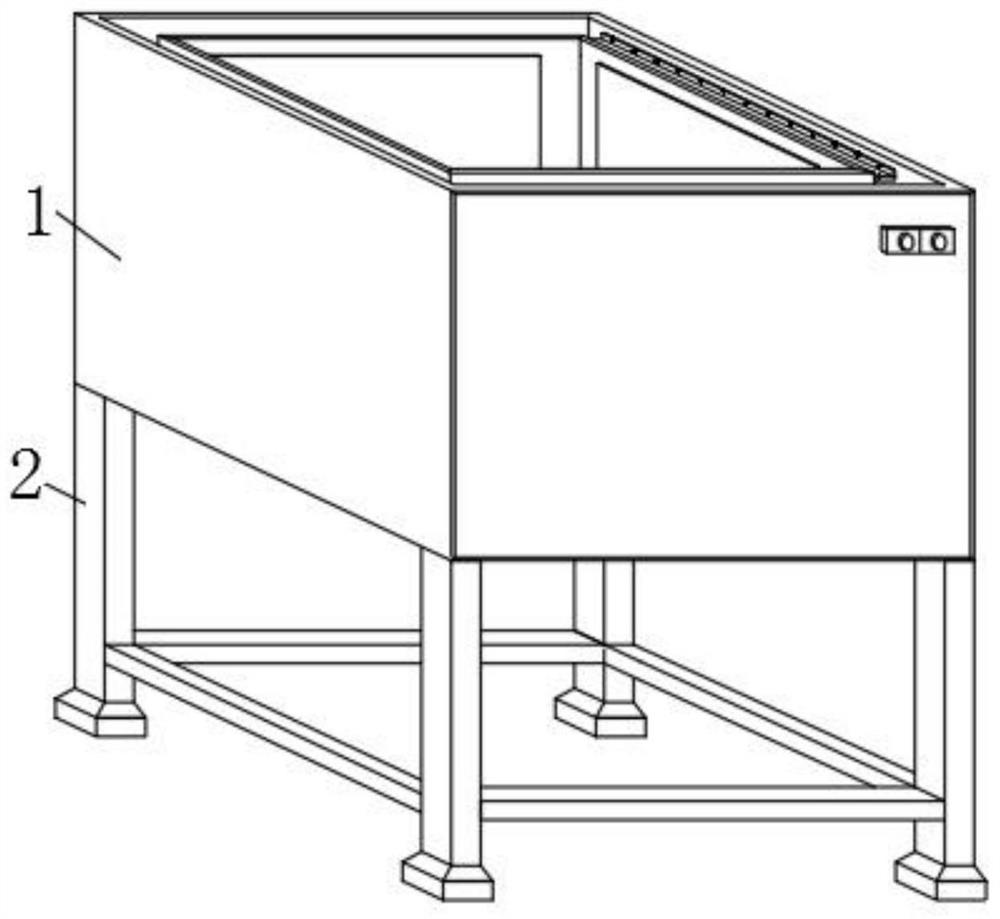
[0041] Such as Figure 3-9 As shown, a crib with an anti-collision device includes a bed body 1, and two buttons are arranged on the front of the bed body 1, and one button is used to control the opening and closing of the micro-motor 703, thereby controlling the stillness of the built-in shaker 5 and Shake, the other button is used to control the expansion and contraction of the electric push rod 17, thereby controlling the angle formed by the backing plate 11 and the bottom plate 9, and the two buttons are electrically connected to the output ends of the micro motor 703 and the electric push rod 17 respectively through wires , the four corners of the bottom surface of the bed 1 are equipped with a base 2, the base 2 is used to support the bed 1, and the two inner walls of the bed 1 are fixed with baffles 3 by bolts to prevent children from stretching their hands when playing. The position between the built-in shaker 5 and the bed body 1 prevents the driving mechanism 7 and t...
Embodiment 2
[0048] The existing cribs only have the function of sleeping. When telling stories or feeding a child, the child needs to be picked up from the bed body 1 and placed on the child seat, so that the child can be normally fed and other operations, resulting in Single function, low cost performance;
[0049] Such as Figure 10-13 As shown, the difference between this embodiment and Embodiment 1 is that the front end of the bottom plate 9 is hinged with a backing plate 11, and the two inner side walls of the built-in shaker 5 are fixedly equipped with L-shaped plates 12, and the two L-shaped connecting plates 701 are positioned on the backing plate 11. Both sides of the board 11 provide support for it, and two symmetrical connecting blocks 13 are fixedly installed on the bottom surface of the board 11, and two symmetrical fourth sliding bars 14 are fixedly installed between the adjacent sides of the two connecting blocks 13 The outer surfaces of the two fourth sliding rods 14 are ...
Embodiment 3
[0051] When using the built-in rocker 5, since each child has different sleep conditions, the most suitable shaking range for each child is also different. If the swing range cannot be automatically adjusted, the built-in rocker 5 is difficult to be suitable for all children ;
[0052] Such as Figure 14 As shown, the difference between this embodiment and Embodiment 1 and Embodiment 2 is that a plurality of threaded holes 711 are provided between the front and back of the drive turntable, and the plurality of thread holes 711 are distributed on the surface of the drive turntable 705 in a row. And the distance between the adjacent threaded holes 711 is equal, one side of the orbiting slide bar 706 is threadedly connected with the threaded hole 711, and the other side of the orbiting slide bar 706 is movably connected with the inner wall of the orbiting chute 708, through the drive turntable The surface of 705 offers a plurality of threaded holes 711, so that the orbiting slid...
PUM
 Abstract
Description
Claims
Application Information
 - R&D
- Intellectual Property
- Life Sciences
- Materials
- Tech Scout
- Unparalleled Data Quality
- Higher Quality Content
- 60% Fewer Hallucinations
Browse by: Latest US Patents, China's latest patents, Technical Efficacy Thesaurus, Application Domain, Technology Topic, Popular Technical Reports.
© 2025 PatSnap. All rights reserved.Legal|Privacy policy|Modern Slavery Act Transparency Statement|Sitemap|About US| Contact US: help@patsnap.com


