
Vehicle anti-lock control method and system based on driver intention recognition

A technology of driver's intention and control method, applied in the field of vehicle anti-lock braking control method and system based on driver's intention recognition

Inactive Publication Date: 2021-07-06
DONGFENG LIUZHOU MOTOR
View PDF5 Cites 1 Cited by
  • Summary
  • Abstract
  • Description
  • Claims
  • Application Information

AI Technical Summary

Problems solved by technology

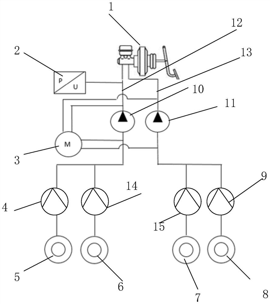
[0004] Embodiments of the present invention provide a vehicle anti-lock brake control method and system based on driver intention recognition, which can solve the problem that the driver cannot trigger the anti-lock brake function in emergency situations due to insufficient strength of the driver himself, and improve vehicle safety

Method used


Image

  • Vehicle anti-lock control method and system based on driver intention recognition
  • Vehicle anti-lock control method and system based on driver intention recognition

Examples


Embodiment Construction

[0022] The following will clearly and completely describe the technical solutions in the embodiments of the present invention with reference to the accompanying drawings in the embodiments of the present invention. Obviously, the described embodiments are only some, not all, embodiments of the present invention. Based on the embodiments of the present invention, all other embodiments obtained by those of ordinary skill in the art without creative efforts shall fall within the protection scope of the present invention.

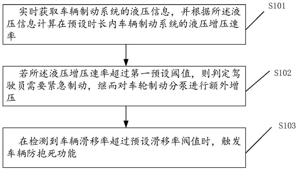
[0023] like figure 1 As shown, an embodiment of the present invention provides a vehicle anti-lock braking control method based on driver intention recognition, which at least includes the following steps:

[0024] Step S101: Acquiring hydraulic pressure information of the vehicle braking system in real time, and calculating the hydraulic pressure boost rate of the vehicle braking system within a preset time period according to the hydraulic pressure informatio...


PUM


Abstract

The invention discloses a vehicle anti-lock control method and system based on driver intention recognition, and the method comprises the steps: obtaining the hydraulic information of a vehicle braking system in real time, and calculating the hydraulic pressurization rate of the vehicle braking system within a preset time period according to the hydraulic information; if the hydraulic pressurization rate exceeds a first preset threshold value, judging that a driver needs emergency braking, and then performing additional pressurization on a wheel brake cylinder; and when it is detected that the vehicle slip rate exceeds the preset slip rate threshold value, triggering the vehicle anti-lock function. By implementing the method, the problem that the anti-lock function cannot be triggered in emergency due to insufficient strength of a driver can be solved, and the vehicle use safety is improved.

Description

technical field [0001] The invention relates to the technical field of vehicle anti-lock braking systems, in particular to a vehicle anti-lock braking control method and system based on driver intention recognition. Background technique [0002] At present, the brake system uses the principle of pedal lever and the form of air pressure difference or motor assist. After the driver's brake pedal force is amplified several times, the input is converted into hydraulic pressure by the brake master cylinder, and then the brake is controlled by the brake cylinder. The dynamic hydraulic pressure is converted into braking force and acts on the wheels. Between the brake master cylinder and the brake cylinder, a hydraulic control unit is connected in series through the brake pipeline. The hydraulic control unit realizes the anti-lock braking control function through an algorithm by monitoring the changes in the wheel speeds of the four wheels. This technology requires the driver to st...

Claims


Application Information

Patent Timeline
IPC IPC(8): B60T8/1755B60T13/74
CPCB60T8/1755B60T8/17551B60T13/745
Inventor 覃权中龙文陈锐李伟伟杨继业覃健蓝伟谢莹莹晏金美梁瑞舟梁宝梯陈裴陈江深罗斯宇钟永普王芳
Owner DONGFENG LIUZHOU MOTOR
Learn More