Fresh air ventilator air duct structure and fresh air ventilator

A technology for fresh air fans and air ducts, applied in mechanical equipment, space heating and ventilation, heating and ventilation hoods/covers, etc., and can solve problems such as decreased fan stability

Active Publication Date: 2021-07-06
GREE ELECTRIC APPLIANCES INC
View PDF9 Cites 0 Cited by
  • Summary
  • Abstract
  • Description
  • Claims
  • Application Information

AI Technical Summary

Problems solved by technology

[0003] In order to solve the technical problem in the above-mentioned prior art that the speed of the fan needs to be increased to achieve...

Method used


Image

  • Fresh air ventilator air duct structure and fresh air ventilator
  • Fresh air ventilator air duct structure and fresh air ventilator
  • Fresh air ventilator air duct structure and fresh air ventilator

Examples


Embodiment Construction

[0021] In order to make the technical problems, technical solutions and beneficial effects to be solved by the present invention clearer, the present invention will be further described in detail below in conjunction with the accompanying drawings and embodiments. It should be understood that the specific embodiments described here are only used to explain the present invention, not to limit the present invention.

[0022] The principle and structure of the present invention will be described in detail below in conjunction with the drawings and embodiments.

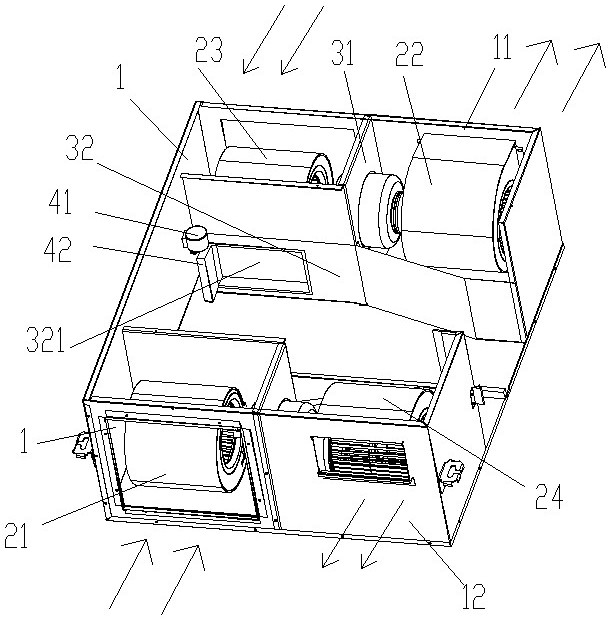
[0023] Such as figure 1 As shown, the present invention proposes a fresh air duct structure, including: a housing, a fresh air duct and an exhaust air duct. One side of the casing is the indoor side 11 , and the opposite side is the outdoor side 12 . The indoor side 11 of the housing is provided with a fresh air outlet and an exhaust air inlet side by side, and the outdoor side 12 of the housing is provided with a fresh...


PUM


Abstract

The invention discloses a fresh air ventilator air duct structure and a fresh air ventilator. The fresh air ventilator air duct structure comprises a shell, a fresh air duct and an exhaust air duct, wherein the fresh air duct and the exhaust air duct communicate with the indoor side and the outdoor side of the shell. Fan assemblies with the opposite air inlet and outlet directions are arranged at a fresh air opening and an exhaust opening of the indoor side and/or the outdoor side of the shell correspondingly. According to the fresh air ventilator air duct structure and the fresh air ventilator, the fan assemblies with the opposite air inlet and outlet directions are arranged on the same side of the fresh air ventilator at the same time, the same or different fan structures can be adopted, and the purpose of improving the air inlet and exhaust static pressure through two-stage pressurization is achieved. A pressurization fan does not need to be adopted, the fan can operate in a high-energy-efficiency area to the maximum extent, the motor efficiency is improved, and the influence of fan rotation vibration is reduced. By adjusting the fan motor rotating speed, the airflow velocity and the airflow direction, automatic adjustment of the inlet and outlet static pressure is achieved, and the comfort of a system is improved.

Description

technical field [0001] The invention relates to the technical field of fresh air blowers, in particular to a fresh air duct structure and the fresh air blower. Background technique [0002] The existing all-heat fresh air intake and exhaust systems use independent single fans to organize the flow field. When the static pressure required by the system increases, it is necessary to increase the fan speed to achieve high static pressure, resulting in increased noise during system operation, seriously affecting the surrounding environment, and at the same time resulting in high motor power, increased motor vibration, fan instability, stalling, and system failure. A series of problems such as increased heat transfer resistance and low heat recovery efficiency. Contents of the invention [0003] In order to solve the technical problem in the above-mentioned prior art that the speed of the fan needs to be increased to achieve high static pressure, resulting in a decrease in the ...

Claims


Application Information

Patent Timeline
IPC IPC(8): F24F1/0007F24F1/0035F24F11/64F24F11/74F24F13/20F24F13/24F24F110/40
CPCF24F1/0007F24F1/0035F24F11/64F24F11/74F24F13/20F24F13/24F24F2110/40F24F2013/247Y02B30/70
Inventor 兰刚迟亚玲高朋范磊王康
Owner GREE ELECTRIC APPLIANCES INC
Why Eureka
Try Eureka