Supercharge Your Innovation With Domain-Expert AI Agents!

Flatness and roughness detection recorder and detection analysis method

A technology of roughness and flatness, which is used in the field of flatness and roughness detection recorders and detection and analysis, which can solve problems such as low work efficiency, spending a lot of time, and inability to perform detection at the same time.

Inactive Publication Date: 2021-07-06
秦皇岛领思科技有限公司
View PDF0 Cites 0 Cited by
  • Summary
  • Abstract
  • Description
  • Claims
  • Application Information

AI Technical Summary

Problems solved by technology

[0004] Generally, the cooperation of two or more precision parts will have certain requirements for flatness and roughness. However, when testing product flatness or roughness, it is often impossible to test at the same time, and it is impossible to record in real time while testing, so that the operator can It takes a lot of time to further check and repair, and even needs to be re-tested, resulting in relatively low work efficiency

Method used


Image

  • Flatness and roughness detection recorder and detection analysis method
  • Flatness and roughness detection recorder and detection analysis method
  • Flatness and roughness detection recorder and detection analysis method

Examples


Embodiment 1

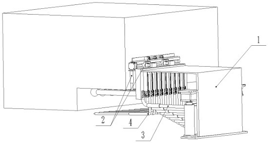
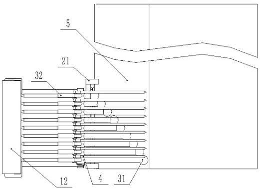
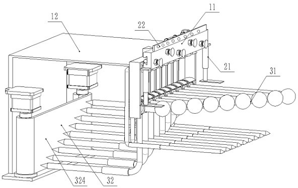
[0050] see Figure 1 to Figure 10 , this embodiment is used to detect the flatness and roughness of one of the sides of the larger width groove provided on the workpiece, specifically: a flatness and roughness detection recorder, including a mounting frame 1, a reference plane alignment device 2. The plane 5 to be measured, in this embodiment, the outer adjacent surface of the plane 5 to be measured is used as the installation datum plane, and the mounting frame 1 includes: a datum plane mounting frame 11 and a connecting frame 12, and the datum plane mounting frame 11 is fixed on the mounting datum surface and is connected with the connecting frame 12 in rotation; the reference plane aligning device 2 includes: a parallel aligning device 21 and a vertical aligning device 22; The alignment device 22 is installed on the top of the datum mounting frame 11; the plane measurement recording mechanism 3 is installed below the connecting frame 12, which includes: a measuring device 3...

Embodiment 2

[0068] Such as Figure 11 As shown, this embodiment is used to detect the flatness and roughness of one of the sides of the groove with a smaller width on the workpiece, specifically: the marking telescopic pen end 4022 in the U-shaped marking assembly 402 is contacted with the detection workpiece groove Both sides are on the same plane reference plane, and other structural principles are the same as above, and will not be repeated here.

[0069] The detection and analysis method of the flatness and roughness detection recorder of the present invention is specifically as follows:

[0070] The first step, on-site inspection:

[0071] The flatness and roughness detection recorder is first fixed on the adjacent surface (reference plane) of the plane 5 to be tested by fixing the telescopic suction cup 114, and the parallel test plate 212 is controlled to fit the plane 5 to be tested by rotating the telescopic cylinder 211 in the parallel alignment device 21 To detect whether the...


PUM


Abstract

The invention relates to a flatness and roughness detection recorder and a detection analysis method. The flatness and roughness detection recorder comprises a mounting frame, a reference surface alignment device, a plane measurement recording mechanism and a field recording device; the mounting frame is divided into a reference surface mounting frame and a connecting frame which are rotationally connected, and the reference surface alignment device is mounted on the reference surface mounting frame and used for alignment mounting of the whole and a reference surface; the plane measurement recording mechanism and the field recording device are arranged below the connecting frame and are used for detecting the plane to be measured and recording planeness and roughness conditions; the plane measuring and recording mechanism includes a measuring device and a recording device which are matched with each other to detect the flatness of the side surface of the part and record and store the detection condition in real time, so that archiving, checking and researching of detection data are facilitated; the on-site recording device can carry out on-site recording on the overall condition of the plane to be measured, so that an operator can conveniently and rapidly recognize the bulge, the sunken point and the general position of the bulge and the sunken point, and the repairing efficiency of the operator is greatly improved.

Description

technical field [0001] The invention relates to the technical field of flatness and roughness detection, in particular to a flatness and roughness detection recorder and a detection and analysis method. Background technique [0002] Flatness refers to the deviation of the macro-convex height of the substrate from the ideal plane; flatness is an index that limits the amount of variation between the actual plane and the ideal plane, and is used to control the shape error of the measured actual plane; [0003] Surface roughness refers to the small spacing and the unevenness of tiny peaks and valleys on the processed surface. The distance (wave distance) between two peaks or two valleys is very small (below 1mm), which belongs to the microscopic geometric shape error; the surface The smaller the roughness, the smoother the surface. [0004] Generally, the cooperation of two or more precision parts will have certain requirements for flatness and roughness. However, when testing ...

Claims


Application Information

Patent Timeline
IPC IPC(8): G01B5/28B43K29/00
CPCB43K29/00G01B5/28
Inventor 王国威曹佳男暴伟杰
Owner 秦皇岛领思科技有限公司
Features
  • R&D
  • Intellectual Property
  • Life Sciences
  • Materials
  • Tech Scout
  • Unparalleled Data Quality
  • Higher Quality Content
  • 60% Fewer Hallucinations
Learn More