Driving method and driving circuit of Mini LED backlight module and display device

A technology of backlight module and driving method, which is applied to static indicators, instruments, etc., and can solve problems such as mini LED backlight current fluctuations

Pending Publication Date: 2021-07-06
TCL CHINA STAR OPTOELECTRONICS TECH CO LTD
View PDF14 Cites 3 Cited by
  • Summary
  • Abstract
  • Description
  • Claims
  • Application Information

AI Technical Summary

Problems solved by technology

[0005] In order to solve the above-mentioned problem of large current fluctuations when the mini LED backlight is working, embodim

Method used


Image

  • Driving method and driving circuit of Mini LED backlight module and display device
  • Driving method and driving circuit of Mini LED backlight module and display device
  • Driving method and driving circuit of Mini LED backlight module and display device

Examples


Embodiment Construction

[0033] The technical solutions in the embodiments of the present application will be clearly and completely described below in conjunction with the drawings in the embodiments of the present application. Apparently, the described embodiments are only some of the embodiments of this application, not all of them. Based on the embodiments in this application, all other embodiments obtained by those skilled in the art without making creative efforts belong to the scope of protection of this application.

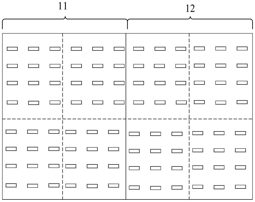
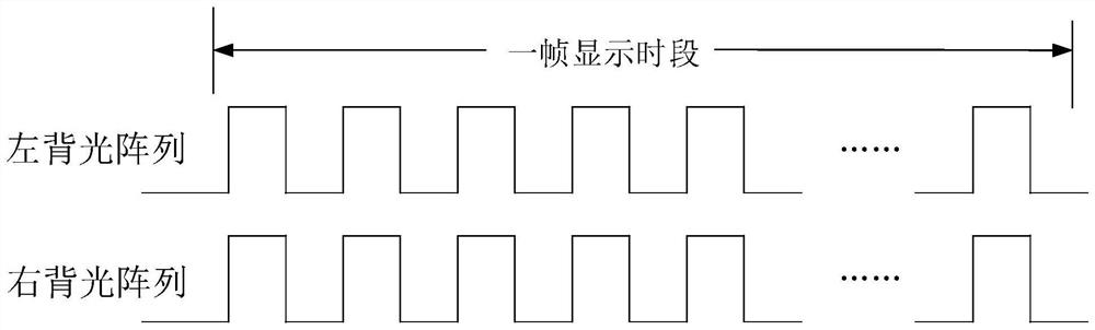
[0034] Such as figure 1 As shown, taking the mini LED backlight module including left and right backlight partitions as an example, within one frame display time, the left backlight partition 11 and the right backlight partition 12 are simultaneously lit, that is, the LEDs in the same row of left and right backlights work at the same time, figure 2 It is a schematic diagram of the timing sequence of the data signal of the mini LED backlight module in the prior art, such as f...


PUM


Abstract

The invention provides a driving method and driving circuit of a mini LED backlight module and a display device. The mini LED backlight module comprises k horizontally-spliced backlight partitions, and according to the driving method, in each frame of display time period, when one scanning signal is provided according to a preset time sequence to scan one row of light-emitting elements of the mini LED backlight module, data signals are sequentially input to the first to kth backlight partitions in a staggered manner according to the brightness information, so that the light-emitting elements in the rows of the first to kth backlight partitions work at the same time until all the light-emitting elements in the mini LED backlight module are driven to work. In this way, each row of light-emitting elements originally needing to work at the same time in the mini LED backlight module are split into a plurality of backlight partitions where the row of light-emitting elements work at the same time, so that the problem that backlight current fluctuation is too large when all rows of light-emitting elements in the mini LED backlight module are turned on at the same time is solved.

Description

technical field [0001] The present application relates to the field of display technology, and in particular to a driving method, a driving circuit and a display device of a mini LED backlight module. Background technique [0002] Mini LED technology can be understood as a fully upgraded version of LCD. The backlight layer of mini LED can accommodate more LEDs per unit area, thereby greatly increasing the number of backlight sources. Therefore, the design of regional brightness adjustment can be carried out, so that LEDs can be turned off in individual areas. In order to achieve complete black, it not only reduces power consumption, but also achieves ultra-high contrast and fine dynamic distribution due to the increase in the number of LEDs per unit area, making the bright field brighter and the dark field darker, thus making the display effect better meticulous. [0003] Currently, figure 1 It is a structural schematic diagram of a mini LED backlight module in the prior a...

Claims


Application Information

Patent Timeline
IPC IPC(8): G09G3/34
CPCG09G3/3426
Inventor 王照刘金风
Owner TCL CHINA STAR OPTOELECTRONICS TECH CO LTD
Why Eureka
Try Eureka