Intensity modulation method and intensity modulator of stable decoy state pulse
An intensity modulator and pulse intensity technology, which is applied in the field of quantum communication, can solve the security problems, differences, and decoy pulse voltage fluctuations of the pulse intensity modulation quantum key distribution system.
- Summary
- Abstract
- Description
- Claims
- Application Information
AI Technical Summary
Problems solved by technology
Method used
Image
Examples
Embodiment approach 1
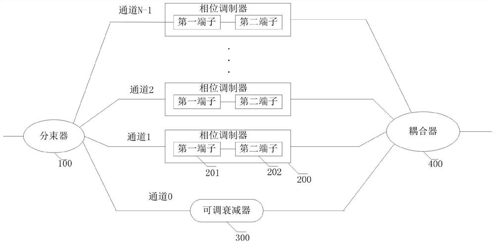
[0062] refer to figure 1 , shows a schematic diagram of the structure of an intensity modulator that stabilizes the decoy state, and its intensity modulator includes:
[0063] A beam splitter 100 for splitting input pulses into multiple channels, wherein N-1 channels are provided with a phase modulator 200, and one channel not provided with a phase modulator is provided with an adjustable attenuator 300, and each channel The coupler 400 connected to the channel, N is a positive integer, indicating the number of channels;
[0064] Wherein, the phase modulator includes: a first terminal 201 for loading a DC voltage and a second terminal 202 for loading a radio frequency signal.
[0065] Wherein, the first terminal loaded with a DC voltage may be a Bias terminal, and the second terminal loaded with a radio frequency signal may be an RF (English full name: Radio Frequency, Chinese full name: radio frequency) terminal.
[0066] Wherein, the beam splitter is a 1*N beam splitter, t...
Embodiment approach 2
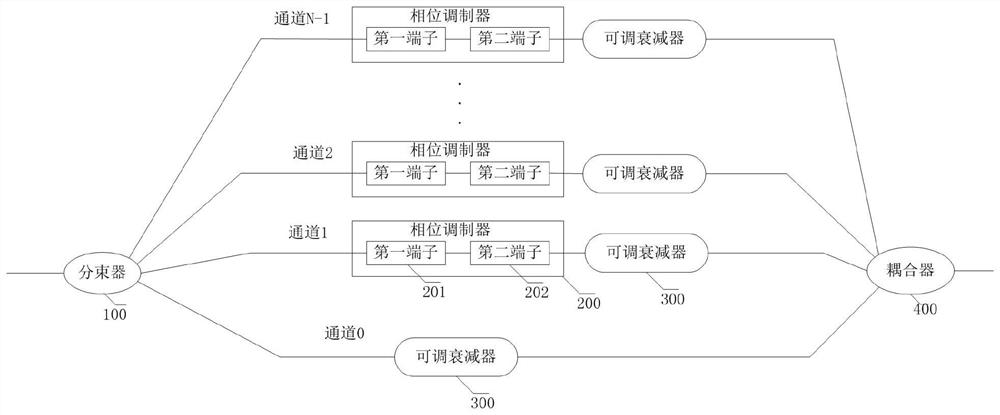
[0069] refer to figure 2 , showing another structural schematic diagram of a stable decoy state intensity modulator, the intensity modulator includes:
[0070] A beam splitter 100 for dividing the input pulse into multiple channels, wherein each channel is provided with an adjustable attenuator 300, N-1 channels are provided with a phase modulator 200, and each channel is connected to Coupler 400, wherein, N is a positive integer, representing the number of channels;
[0071] The phase modulator 200 includes: a first terminal 201 loaded with a DC voltage and a second terminal 202 loaded with a radio frequency signal.
[0072] Wherein, the first terminal loaded with a DC voltage may be a Bias terminal, and the second terminal loaded with a radio frequency signal may be an RF (English full name: Radio Frequency, Chinese full name: radio frequency) terminal.
[0073] Wherein, the beam splitter is a 1*N beam splitter, that is, after the input pulse is input to the beam splitter...
PUM
 Abstract
Description
Claims
Application Information
 - R&D
- Intellectual Property
- Life Sciences
- Materials
- Tech Scout
- Unparalleled Data Quality
- Higher Quality Content
- 60% Fewer Hallucinations
Browse by: Latest US Patents, China's latest patents, Technical Efficacy Thesaurus, Application Domain, Technology Topic, Popular Technical Reports.
© 2025 PatSnap. All rights reserved.Legal|Privacy policy|Modern Slavery Act Transparency Statement|Sitemap|About US| Contact US: help@patsnap.com


