Camera module and electronic equipment

A technology of camera module and lens assembly, which is applied in branch equipment, television, electrical components, etc., and can solve the problems of reducing the height of the camera module

Active Publication Date: 2021-07-06
VIVO MOBILE COMM CO LTD
View PDF7 Cites 1 Cited by
  • Summary
  • Abstract
  • Description
  • Claims
  • Application Information

AI Technical Summary

Problems solved by technology

However, the above-mentioned carrier only plays the role of carrying the optical filter and the anti-reflection member, and does not help in reducing the height of the camera module.

Method used


Image

  • Camera module and electronic equipment
  • Camera module and electronic equipment
  • Camera module and electronic equipment

Examples


specific Embodiment 1

[0063] Specific embodiment one: as Figure 5 As shown, the refractive index distribution of the carrier 106 may vary along the optical axis L, and the darker the color, the greater the refractive index. Using the microelement method, the carrier 106 is sliced, and the division accuracy of the slice is higher ( Figure 5 N in the middle corresponds to the number of slices in the L direction of the optical axis. The larger N is, the smaller the calculation error is. In practice, it can be considered according to specific needs. For example, the optical path change of each micro-element can be set as one percent of the center wavelength, thereby setting a specific N value.

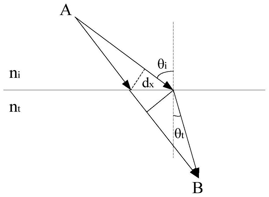
[0064] Typical conic-type refractive index profile: where z is the optical axis, n 0 is the refractive index at z=0, and a is the distribution coefficient. The analytical solution of the corresponding path is:

[0065]

[0066]

[0067] where p 0 , l 0 、m 0 is the direction cosine of the initia...

specific Embodiment 2

[0068] Specific embodiment two: as Figure 6 As shown, in a plane perpendicular to the optical axis L, the refractive index of the carrier 106 gradually changes around the optical axis L, and the darker the color, the larger the refractive index.

[0069] The index of refraction is consistent with the shade of the color, throughout the text. At this time, the micro-element slice will be parallel to the optical axis L, and the slice precision is similar to that in method 1, and the optical path can be controlled within one hundredth of a wavelength ( Figure 6 N in the middle corresponds to the number of slices in the radial direction of the optical axis L, the larger N is, the smaller the calculation error is, and it can be considered according to specific needs, for example, the optical path change of each micro-element can be set to one percent Center wavelength, so as to set a specific N value. For the basic quadratic index profile: Relevant parameters are consistent wi...

specific Embodiment 3

[0073] Specific embodiment three: as Figure 7 As shown, the refractive index distribution of the carrier 106 changes along the optical axis L, and in a plane perpendicular to the optical axis L, the refractive index of the carrier 106 also gradually changes around the center of the optical axis L, and the darker the color The greater the refractive index. In this case, binary slicing is required.

[0074] Figure 7 Among them, M and N respectively correspond to the number of slices in the direction of the optical axis L and the radial direction, and it is also necessary to ensure an optical path difference with an accuracy of one hundredth of a wavelength. This two-dimensional change mode makes it have more degrees of freedom in light manipulation, and is more helpful to the design optimization of the bearing member 106 .

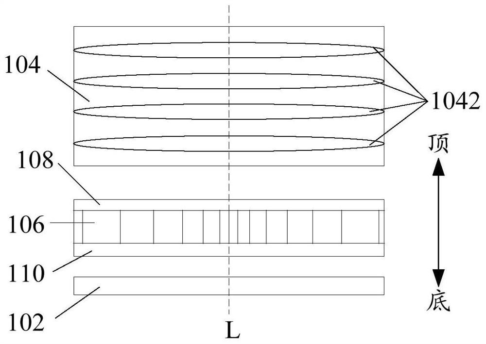
[0075] The above three specific implementation methods all deal with the carrier 106 , so that the number of lenses 1042 in the lens assembly 104 can b...


PUM


Abstract

The invention discloses a camera module and electronic equipment, the camera module comprises a photosensitive member, a lens assembly and a bearing member, the lens assembly is arranged at the top of the photosensitive member, the bearing member is arranged between the lens assembly and the photosensitive member, the refractive index of the bearing member gradually changes, and the propagation path of light emitted from the lens assembly in the bearing member is a curve. The light passes through the bearing member and then is emitted to the photosensitive member. According to the embodiment of the invention, the refractive index of the bearing part is designed to be gradually changed, so that the bearing part functionally replaces the last lens in the original lens assembly, at least one lens of the original lens assembly can be reduced, the height of the camera module is reduced, and light and thin design of electronic equipment such as a mobile phone can be realized.

Description

technical field [0001] The present application relates to the technical field of electronic equipment, in particular, to a camera module and electronic equipment. Background technique [0002] At present, users have higher and higher requirements for the performance of camera modules in various aspects (for example: high pixel, high resolution, large aperture). Therefore, the number of lenses in the lens assembly is increasing, which directly leads to the height of the camera module is getting higher and higher, making the thickness of electronic devices such as mobile phones that should be camera modules increasing, and even the convexity of the camera module It has become a norm, which does not meet the demand for thinner and lighter mobile phones. [0003] In addition, infrared light in ambient light can interfere with the photosensitive element. Therefore, in the related art, a carrier is provided between the lens assembly and the photosensitive member, and an optical ...

Claims


Application Information

Patent Timeline
Patent Type & Authority Applications(China)
IPC IPC(8): H04N5/225H04M1/02
CPCH04M1/0264H04N23/57H04N23/55
Inventor 潘望军
Owner VIVO MOBILE COMM CO LTD
Why Eureka
Try Eureka