Head pelvic ring traction frame

A technology of pelvic ring and traction frame, which is applied in the field of skull and pelvic ring traction frame, can solve the problems of complex disassembly process, troublesome maintenance and cleaning, and reduced practicability, and achieve the effect of convenient maintenance, convenient operation, and simple use

Active Publication Date: 2021-07-09
王孝宾
View PDF5 Cites 0 Cited by
  • Summary
  • Abstract
  • Description
  • Claims
  • Application Information

AI Technical Summary

Problems solved by technology

[0006] The purpose of the present invention is to provide a skull and pelvis ring traction frame to solve the problem that the current commonly used skull and pelvis ring traction frame proposed in the above background technology needs to be disassembled for cleaning after use, and the process of dismantling is complicated. , which makes maintenance and cleaning very troublesome, inconvenient for maintenance, and leads to the problem of reduced practicability

Method used


Image

  • Head pelvic ring traction frame
  • Head pelvic ring traction frame
  • Head pelvic ring traction frame

Examples


Embodiment Construction

[0027] The following will clearly and completely describe the technical solutions in the embodiments of the present invention with reference to the accompanying drawings in the embodiments of the present invention. Obviously, the described embodiments are only some of the embodiments of the present invention, not all of them.

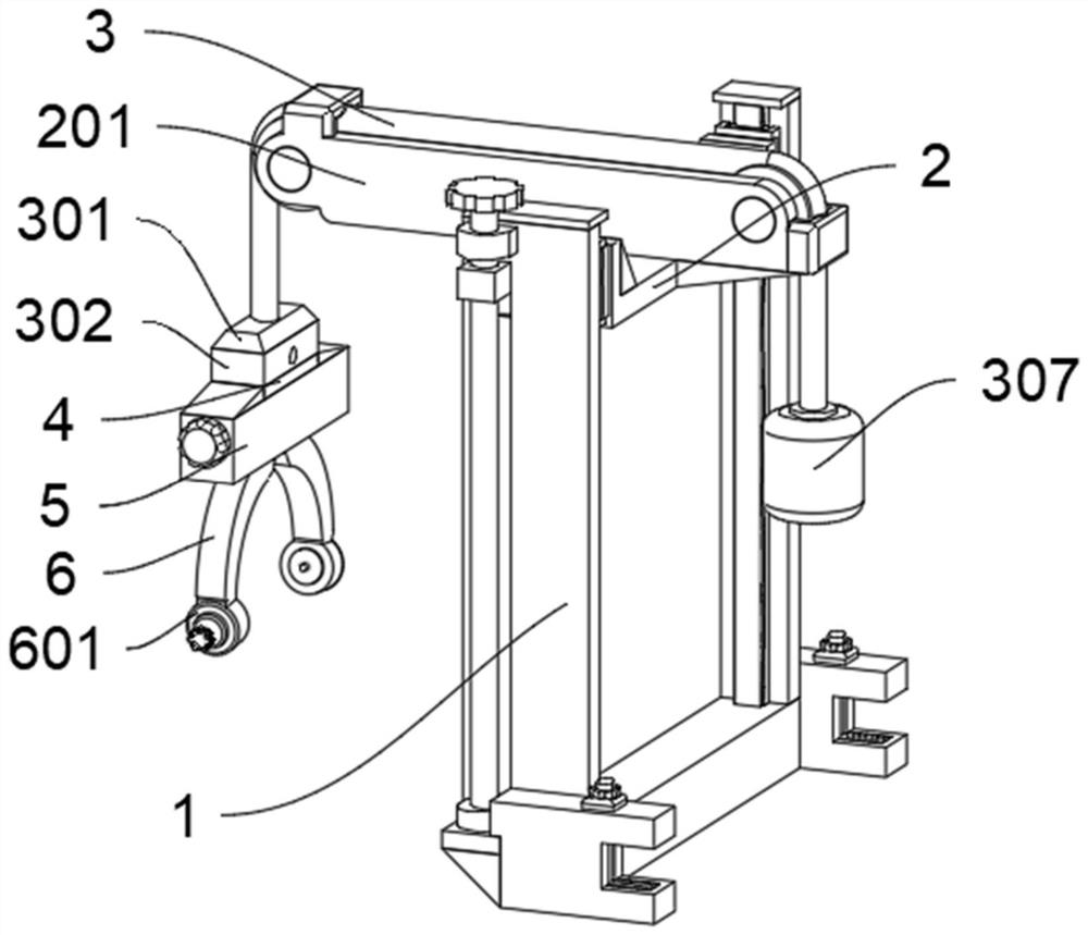
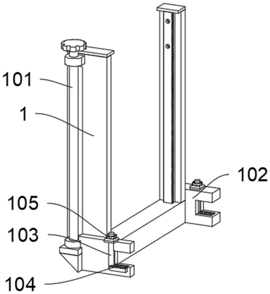
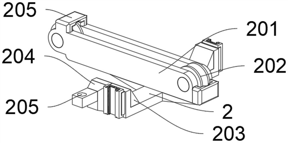
[0028] see Figure 1 to Figure 7 , an embodiment provided by the present invention: a skull-pelvic ring traction frame, including a support frame 1; guide rails are provided on the inside of the support frame 1, and a lifting block 2 is provided outside the guide rails to slide through a slider; the lifting block 2 also includes There are reinforcing block A203, connecting block 204 and connecting protrusion 205; both ends of the lifting block 2 are fixedly provided with reinforcing block A203; the top of the reinforcing block A203 is fixedly connected with the bottom of the connecting frame 201; one side of the lifting block 2 is fixedly provided with a...


PUM


Abstract

The invention discloses a head pelvic ring traction frame, relates to the technical field of traction equipment, and solves the problems that after a common head pelvic ring traction frame at present is used, the whole traction frame needs to be disassembled for cleaning, the disassembly process is complicated, maintenance and cleaning are very troublesome, maintenance is inconvenient, and the practicability is reduced. The utility model discloses a head pelvic ring traction frame which comprises a supporting frame. Guide rails are arranged on the inner sides of the supporting frames, and lifting blocks are slidably arranged outside the guide rails through sliding blocks. A connecting frame is fixedly arranged at the top of the lifting block; and rolling wheels are rotationally arranged at the two ends of the connecting frame. A rotating screw rod C is used, the screw rod C drives a clamping plate to move inwards, a connecting and fixing block makes contact with limitation, then a traction frame is detached, the traction frame is cleaned and disinfected, the traction frame is conveniently maintained, and the practicability of the traction frame is improved.

Description

technical field [0001] The invention relates to the technical field of traction equipment, in particular to a skull and pelvis ring traction frame. Background technique [0002] Skull traction is mainly used to treat cervical spine injuries, especially for patients with cervical spondylolisthesis. Of course, after surgery for patients with cervical spine surgery, especially for patients with cervical disc herniation, cranial traction and external fixation can also be used. Guaranteed surgical results. The specific operation method of cranial traction is to shave all the hair of the patient, then drill holes for fixing screws on the parietal tuberosity on both sides of the patient, install the cranial traction bow, and finally connect one or more traction hammers. [0003] After retrieval, for example, the patent No. CN107397618A discloses that the present invention relates to a traction device, in particular to a cranial tractor and a method of use thereof. The head tracto...

Claims


Application Information

Patent Timeline
Patent Type & Authority Applications(China)
IPC IPC(8): A61B17/66
CPCA61B17/66
Inventor 王孝宾胡佳
Owner 王孝宾
Why Eureka
Try Eureka