Thermal bridge suppression structure for equipment installation

A technology for installing thermal bridges and equipment, which is applied in the field of aircraft thermal structure connection, can solve problems that affect the reliability of electronic equipment inside the equipment, and the temperature rise of the equipment shell, so as to reduce heat transfer, reduce equipment temperature, and suppress thermal bridges Effect

Active Publication Date: 2021-07-09
BEIJING RES INST OF MECHANICAL & ELECTRICAL TECH
View PDF5 Cites 0 Cited by
  • Summary
  • Abstract
  • Description
  • Claims
  • Application Information

AI Technical Summary

Problems solved by technology

On the one hand, the existence of thermal bridges will form hot spots in the cabin, which will adversely affect the thermal environment in the cabin, and on the other hand, it will cause the temperature of the equipment shell to rise, which will affect the reliability of the electronic equipment inside the equipment. Therefore, a thermal bridge suppression measure is needed , to reduce this adverse effect and ensure the safe and reliable operation of the aircraft

Method used


Image

  • Thermal bridge suppression structure for equipment installation

Examples


Embodiment Construction

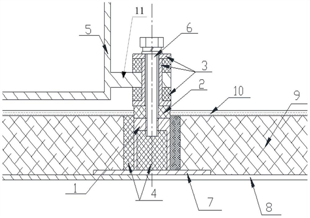
[0011] The present invention will be described in detail below in conjunction with specific examples and accompanying drawings.

[0012] The present invention as figure 1 As shown, an equipment installation thermal bridge suppression structure is provided. The equipment is installed in the air through the adapter tab 11 provided on the equipment housing 5. The adapter tab 11 is connected to the top of the mounting foot 1 through the connecting screw 6. The installation foot 1 is installed inside the thermal protection structure of the equipment compartment shell, and the bottom of the mounting leg 1 is connected to the equipment compartment shell 8 through an adapter gasket. The mounting leg 1 is a thin-walled hollow structure, and pyrolytic Material 4.

[0013] The invention reduces the heat transfer area passing through the heat bridge and the total heat transfer amount passing through the heat bridge through the mounting feet of the hollow structure. The heat transferred ...


PUM


Abstract

The invention provides a thermal bridge suppression structure for equipment installation, wherein equipment is installed in a suspended mode through an adapter lug arranged on an equipment shell, the adapter lug is connected with the top of an installation supporting foot through a connecting screw, the installation supporting foot is installed in an equipment cabin shell thermal protection structure, and the bottom of the installation supporting foot is connected with the equipment cabin shell through an adapter gasket. The installation supporting feet are of a hollow thin-wall structure, and pyrolysis materials are arranged in the inner areas and the outer areas of the installation supporting feet. According to the thermal bridge suppression structure, the hollow structure is adopted for mounting the supporting legs and a suspended mounting mode is adopted, so that heat transferred into a cabin and an equipment shell through a thermal bridge is greatly reduced, and effective thermal protection is realized.

Description

technical field [0001] The invention relates to a thermal bridge suppression structure for equipment installation, and belongs to the technical field of aircraft thermal structure connection. Background technique [0002] As modern aircraft fly faster and faster, for aircraft with thermal structures, the cabin structure faces a severe aerodynamic heating environment, and the mounting feet of equipment in the cabin are generally fixed on the cabin structure, forming a thermal bridge. On the one hand, the existence of thermal bridges creates hot spots in the cabin, which adversely affects the thermal environment in the cabin, and on the other hand, it causes the temperature of the equipment shell to rise, which in turn affects the reliability of the electronic equipment inside the equipment. Therefore, a thermal bridge suppression measure is needed , reduce this adverse effect, and ensure the safe and reliable operation of the aircraft. Contents of the invention [0003] Th...

Claims


Application Information

Patent Timeline
Patent Type & Authority Applications(China)
IPC IPC(8): B64D47/00
CPCB64D47/00
Inventor 方力郭滨张伟堂刘海芳徐永亮张姗
Owner BEIJING RES INST OF MECHANICAL & ELECTRICAL TECH
Why Eureka
Try Eureka