A surveying and mapping drone

A technology of unmanned aerial vehicle and surveying and mapping device, which is applied in the field of surveying and mapping unmanned aerial vehicle, can solve the problems of slowing down the exploration progress, not having a lens cleaning mechanism, and unclear shooting, so as to save manual cleaning, increase the shooting range, and improve the The effect of work efficiency

Active Publication Date: 2021-12-24
甘肃能源化工职业学院
View PDF9 Cites 0 Cited by
  • Summary
  • Abstract
  • Description
  • Claims
  • Application Information

AI Technical Summary

Problems solved by technology

[0002] With the development of the times, people's living standards continue to improve, and people's demand for resources is getting higher and higher. The large-scale development and utilization of mineral resources have brought huge social and economic benefits to mankind. Before mining Surveying and mapping work is required, but due to the complex terrain of the mining area, a surveying and mapping UAV is needed for surveying and mapping; however, in the existing technology, the shooting range of the camera is small, resulting in the need to greatly adjust the unmanned aerial vehicle when surveying and mapping the mining area terrain The surveying and mapping orientation of the drone reduces the working effect of the drone, and the existing surveying and mapping drone does not have a lens cleaning mechanism. When the surveying and mapping drone is in use, the lens will be covered with impurities or water mist on the lens surface , will cause the camera lens to be blurred, resulting in unclear shooting, affecting the geological exploration of personnel, and slowing down the progress of exploration

Method used


Image

  • A surveying and mapping drone
  • A surveying and mapping drone
  • A surveying and mapping drone

Examples


Embodiment 1

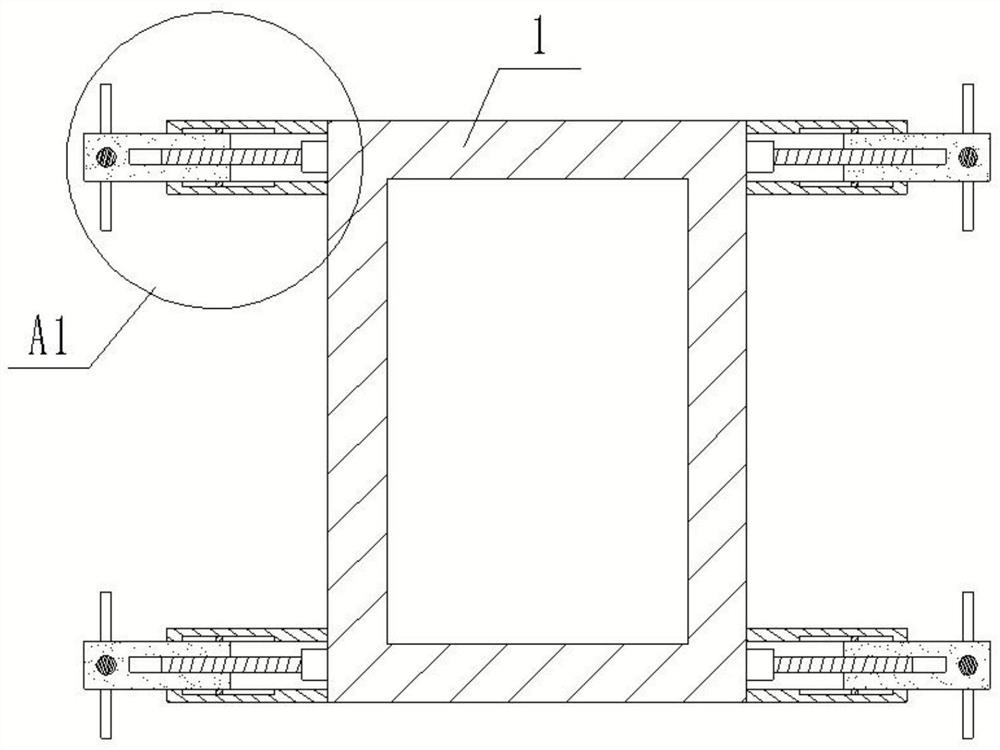
[0037] refer to Figure 1-6 , the present invention provides a surveying and mapping unmanned aerial vehicle, comprising: an unmanned aerial vehicle main body 1, a plurality of driving devices are arranged on the peripheral surface of the unmanned aerial vehicle main body 1, and a surveying and mapping device is arranged at the center of the bottom surface of the unmanned aerial vehicle main body 1;

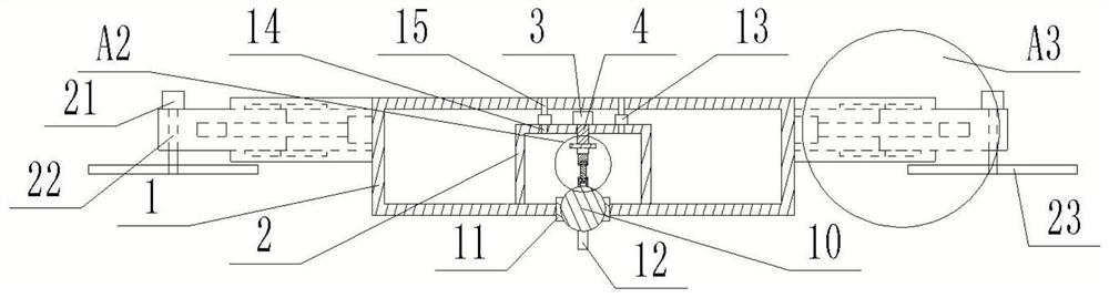
[0038] The surveying and mapping device includes a positioning housing 2, the positioning housing 2 is arranged on the bottom surface of the inner cavity of the main body of the drone 1, the top surface of the positioning housing 2 is fixed with a cylinder 3, and the output shaft of the cylinder 3 runs through One end of the telescopic rod 4 is affixed to the top surface of the positioning housing 2, a positioning plate 5 is affixed to the other end of the telescopic rod 4, and an angle-adjusting motor 6 is affixed to the bottom surface of the positioning plate 5. The output shaf...

Embodiment 2

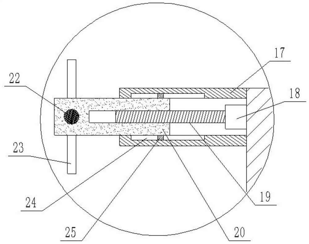
[0053] refer to Figure 7-9 The difference with Embodiment 1 is that the bottom surface of the telescopic cylinder 17 may have a sliding hole 26, and the bottom surface of the driving cylinder 20 is fixedly connected with a connecting rod 27, and the bottom of the connecting rod 27 passes through the sliding hole 26 and is connected to the The inner wall of the sliding hole 26 is slidingly connected, the bottom surface of the connecting rod 27 is fixedly connected with one end of the support rod 28, and the bottom surface of the other end of the support rod 28 is fixedly connected with a rotating shaft 30, and the outer casing of the rotating shaft 30 is provided with a guide fan 31, so The guide fan 31 is rotatably connected with the rotating shaft 30; the guide fan 31 is arranged under the spiral blade 23, which can play the role of concentrating the wind force, can concentrate all the wind force in one direction, and can strengthen the The working efficiency of the spiral b...

Embodiment 3

[0055] refer to Figure 10-11 , The difference with Embodiment 1 and Embodiment 2 is that the bottom surface of the drone main body 1 is fixedly connected with an annular rubber pad 32, the bottom surface of the annular rubber pad 32 is inclined, and the bottom surface of the annular rubber pad 32 An annular fixing plate 33 is affixed, and the bottom surface of the annular fixing plate 33 is equidistantly inclined and affixed with three lowering cylinders 34, and one end of the inner cavity of the lowering cylinder 34 is fixedly connected with a lowering motor 35, and the output end of the lowering motor 35 Fixedly connected with a drop rod 36, the other end of the inner chamber of the drop tube 34 is provided with a limit tube 37, the outer wall of the drop rod 36 is threadedly connected to the inner wall of the limit tube 37, and the bottom surface of the limit tube 37 is provided with A rubber ball 38, the rubber ball 38 is embedded with a pressure sensor 29; the landing tu...


PUM


Abstract

The invention discloses a surveying and mapping unmanned aerial vehicle, comprising: a main body of the unmanned aerial vehicle, a plurality of driving devices are arranged on the peripheral surface of the main body of the unmanned aerial vehicle, and a surveying and mapping device is arranged at the center of the bottom surface of the main body of the unmanned aerial vehicle; the surveying and mapping device includes a positioning Housing, the positioning housing is arranged on the bottom surface of the inner cavity of the main body of the drone, the top surface of the positioning housing is fixed with a cylinder, and the output shaft of the cylinder passes through the top surface of the positioning housing and is fixed with a telescopic rod One end of the telescopic rod is fixedly connected with a positioning plate, the bottom surface of the positioning plate is fixedly connected with an angle-adjusting motor, and the output shaft of the angle-adjusting motor is fixedly connected with one end of a hinged rod, and the The other end is hinged with an adjustment rod, the bottom of the adjustment rod is hinged with a hinge seat, the bottom surface of the hinge seat is fixed with a steering sphere, and the bottom surface of the main body of the drone is provided with a clamping hole, and the clamping hole is fixed A rotating seat is connected, and a camera is fixedly connected to the bottom surface of the steering sphere.

Description

technical field [0001] The invention relates to the technical field of mine area surveying and mapping, in particular to a surveying and mapping drone. Background technique [0002] With the development of the times, people's living standards continue to improve, and people's demand for resources is getting higher and higher. The large-scale development and utilization of mineral resources have brought huge social and economic benefits to mankind. Before mining Surveying and mapping work is required, but due to the complex terrain of the mining area, a surveying and mapping UAV is needed for surveying and mapping; however, in the existing technology, the shooting range of the camera is small, resulting in the need to greatly adjust the unmanned aerial vehicle when surveying and mapping the mining area terrain The surveying and mapping orientation of the drone reduces the working effect of the drone, and the existing surveying and mapping drone does not have a lens cleaning m...

Claims


Application Information

Patent Timeline
Patent Type & Authority Patents(China)
IPC IPC(8): B64D47/08B64C39/02B08B5/02F16M11/12F16M11/18
CPCB64D47/08B64C39/024B08B5/02F16M11/12F16M11/18B64U2101/30B64U10/10
Inventor 付帅
Owner 甘肃能源化工职业学院
Why Eureka
Try Eureka