
Pay-off device

A technology of pay-off device and winding rod, which is applied in the direction of transportation and packaging, delivery of filamentous materials, cable laying equipment, etc., can solve the problems of poor convenience, achieve convenient operation, convenient positioning and connection, and solve the problem of poor convenience Effect

Active Publication Date: 2021-07-09
ZHANJIANG POWER SUPPLY BUREAU OF GUANGDONG POWER GRID CO LTD
View PDF7 Cites 0 Cited by
  • Summary
  • Abstract
  • Description
  • Claims
  • Application Information

AI Technical Summary

Problems solved by technology

[0004] In view of this, the purpose of this application is to provide a wire pay-off device, which effectively solves the technical problem of poor convenience in the prior art

Method used

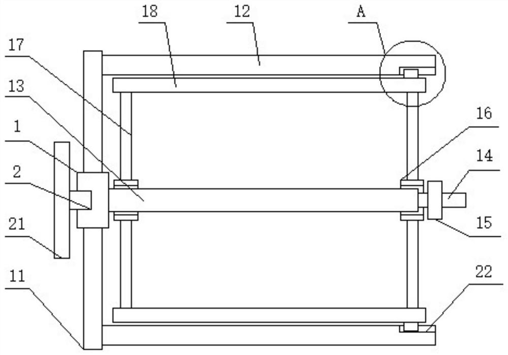
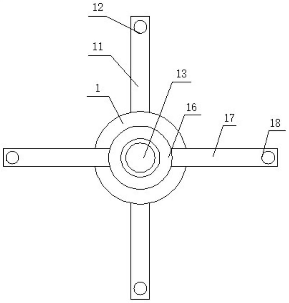
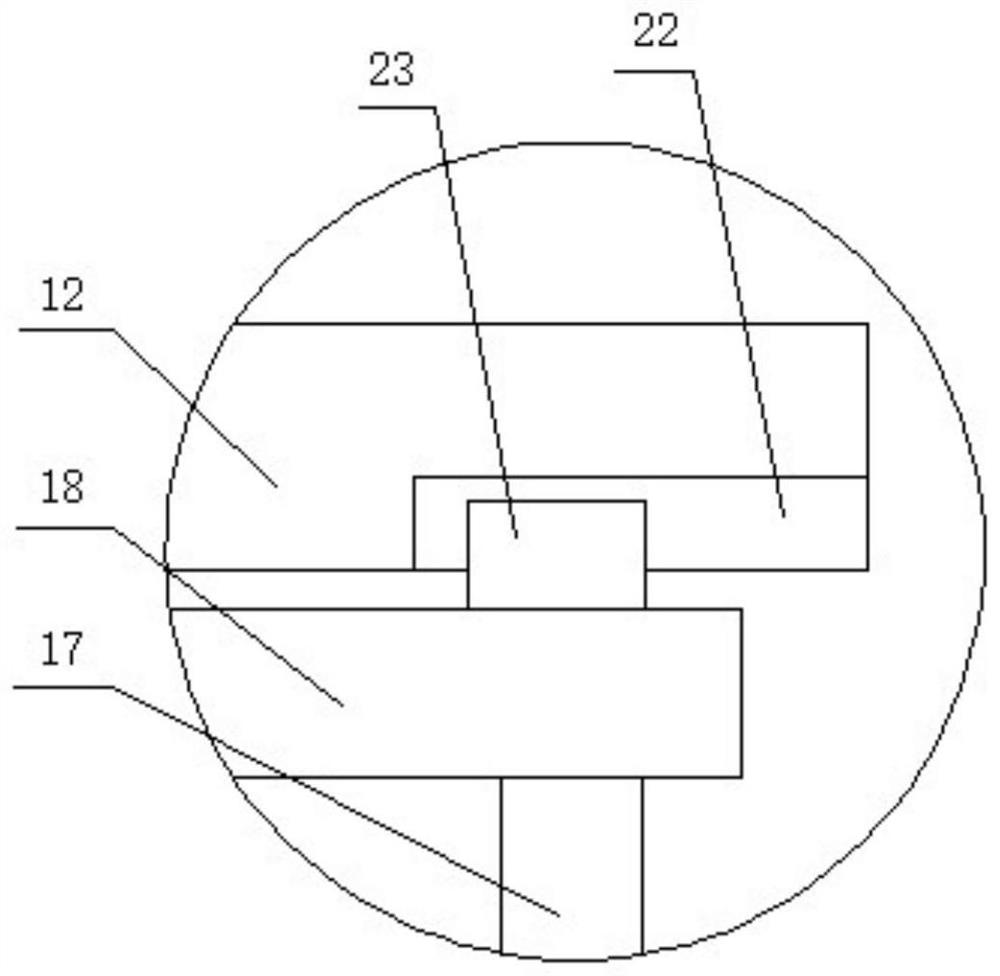

Image

  • Pay-off device
  • Pay-off device
  • Pay-off device

Examples


Embodiment Construction

[0032] The following will clearly and completely describe the technical solutions in the embodiments of the application with reference to the drawings in the embodiments of the application. Apparently, the described embodiments are only some of the embodiments of the application, not all of them. Based on the embodiments in this application, all other embodiments obtained by persons of ordinary skill in the art without making creative efforts belong to the scope of protection of this application.

[0033] In the description of the embodiments of the present application, it should be noted that the terms "center", "upper", "lower", "left", "right", "vertical", "horizontal", "inner", "outer " and other indicated orientations or positional relationships are based on the orientations or positional relationships shown in the drawings, and are only for the convenience of describing the embodiments of the present application and simplifying the description, rather than indicating or i...


PUM


Abstract

The invention relates to the technical field of distribution wire pay-off, in particular to a pay-off device. The pay-off device comprises a connecting block, a center rod, first winding rods and second winding rods; the first end of the center rod is connected with the connecting block, and first connecting rods are arranged on the two sides of the connecting block; each first connecting rod is connected with the corresponding first winding rod, and each first winding rod is parallel to the center rod; a connecting ring is rotationally mounted on the center rod, and second connecting rods are arranged on the two sides of the connecting ring; each second connecting rod is connected with the corresponding second winding rod, and each second winding rod is parallel to the center rod; the distance between each second winding rod and the center rod is smaller than the distance between each first winding rod and the center rod. The technical problem of poor convenience in the prior art is effectively solved.

Description

technical field [0001] The present application relates to the field of distribution wire pay-off technology, in particular to a wire pay-off device. Background technique [0002] In the laying and installation process of distribution lines, bundled wires need to be laid out, and in order to facilitate operation and avoid clutter, a wire-releasing device is generally used to assist positioning and deployment. [0003] However, most of the existing pay-off devices are relatively complicated roller bracket structures, which are not suitable for indoor pay-off, and are not conducive to operation when positioning the connecting wire bundle, and have poor adaptability. Improve. Contents of the invention [0004] In view of this, the purpose of the present application is to provide a wire pay-off device, which effectively solves the technical problem of poor convenience in the prior art. [0005] In order to achieve the above object, the application provides the following techn...

Claims


Application Information

Patent Timeline
Patent Type & Authority Applications(China)
IPC IPC(8): B65H49/18H02G1/06
CPCB65H49/18H02G1/06B65H2701/34
Inventor 符方炫王睿奇
Owner ZHANJIANG POWER SUPPLY BUREAU OF GUANGDONG POWER GRID CO LTD
Learn More