
Bicycle simulation system

a simulation system and bicycle technology, applied in gymnastics, instruments, teaching apparatus, etc., can solve the problems of unfavorable affecting the appearance of the bicycle simulation system, difficult steering handle operation, etc., and achieve the effect of enhancing the realism and enhancing the stability of the signals being transmitted

Inactive Publication Date: 2009-02-17
HONDA MOTOR CO LTD
View PDF20 Cites 22 Cited by
  • Summary
  • Abstract
  • Description
  • Claims
  • Application Information

AI Technical Summary

Benefits of technology

[0012]In the bicycle simulation system, when the steering handle is so configured as to be capable of turning operations and the turning operations are reflected on the scenery displayed on the monitor, the realism is favorably enhanced. In this case, a signal from a steering angle sensor for detecting the turning operations is processed by the controller, in the same manner as the signal from the speed sensor for detecting the simulated velocity, and then supplied to the picture processing computer.
[0017]Such a configuration in which the controller is provided on the frame, not on a turnable portion such as the steering handle, ensures that the feeling during the riding is similar to that in riding a real bicycle. Particularly, the steering handle provides the same light operation feeling and appearance as steering handle of a real bicycle. A steering handle is one of the main characteristic portions in the appearance of a bicycle, not only as viewed from the rider seated astride the saddle but also as viewed from a distance. Therefore, the configuration in which the same appearance as that of a steering handle of a real bicycle can be obtained promises an enhanced realism.
[0018]In this case, preferably, the frame includes a stand as a support member provided at a lower portion of the steering handle. The controller is provided at the stand. The vicinity of the stand would not easily appear in the visual field of the rider, so that the controller does not spoil the appearance. In addition, since a display unit is disposed on the front side of the rider, the arrangement of the controller at the stand ensures that a signal cable for connecting the controller to the display unit is set short. Therefore, the stability of signals being transmitted is enhanced, and it is easy to lay the signal cable around. Furthermore, the vicinity of the stand is a dead space where no other special component part is present. Therefore, even a comparatively large controller can be arranged without influencing the layout of other component parts.
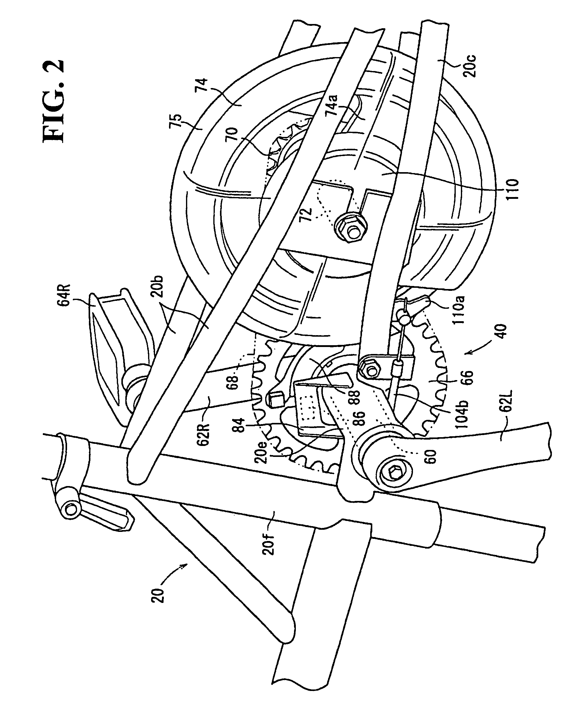
[0021]The rotation speed of the rotary body and the rotation speed of the crankshaft are detected. The difference between the two rotation speeds is determined in consideration of the rotational ratio. Therefore, it is possible to generate an appropriate mimic sound according to a real bicycle and the situation assumed in the simulated cycling, based on the difference. In this case, when a sound obtained by recording the notch sound generated by a one-way clutch is used as the mimic sound, it is possible to generate a sound with higher realism.

Problems solved by technology

When such a comparatively large controller is provided at the steering handle portion, it becomes difficult to operate the steering handle due to the weight.
In addition, the controller may appear in the visual field of the rider, and may unfavorably affect the appearance of the bicycle simulation system.

Method used


Image

  • Bicycle simulation system
  • Bicycle simulation system
  • Bicycle simulation system

Examples


Embodiment Construction

[0043]The bicycle simulation system according to the present invention will now be described in detail with reference to the accompanying drawings. It should be noted that the same reference numerals have been used to identify the same or similar elements throughout the several views.

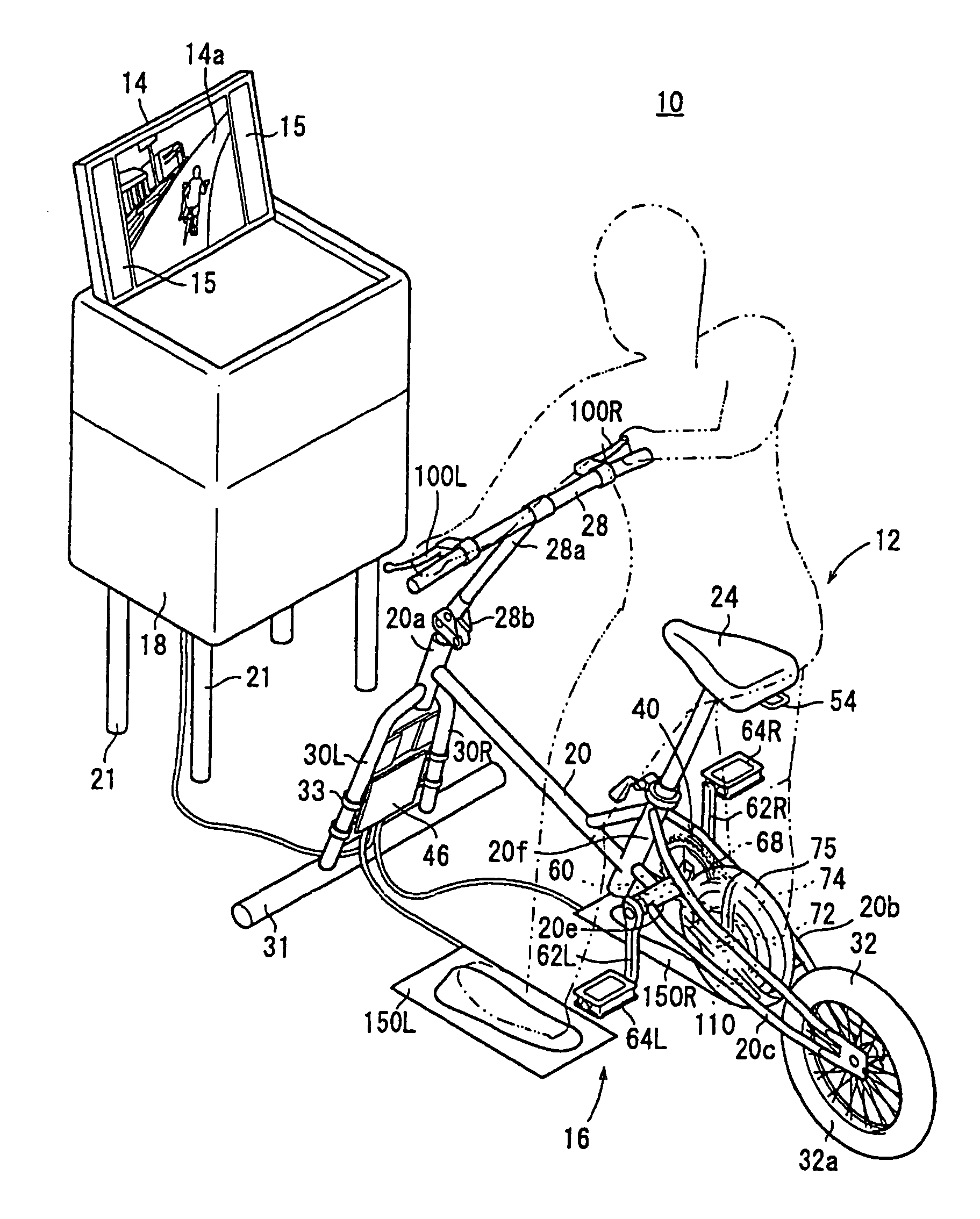
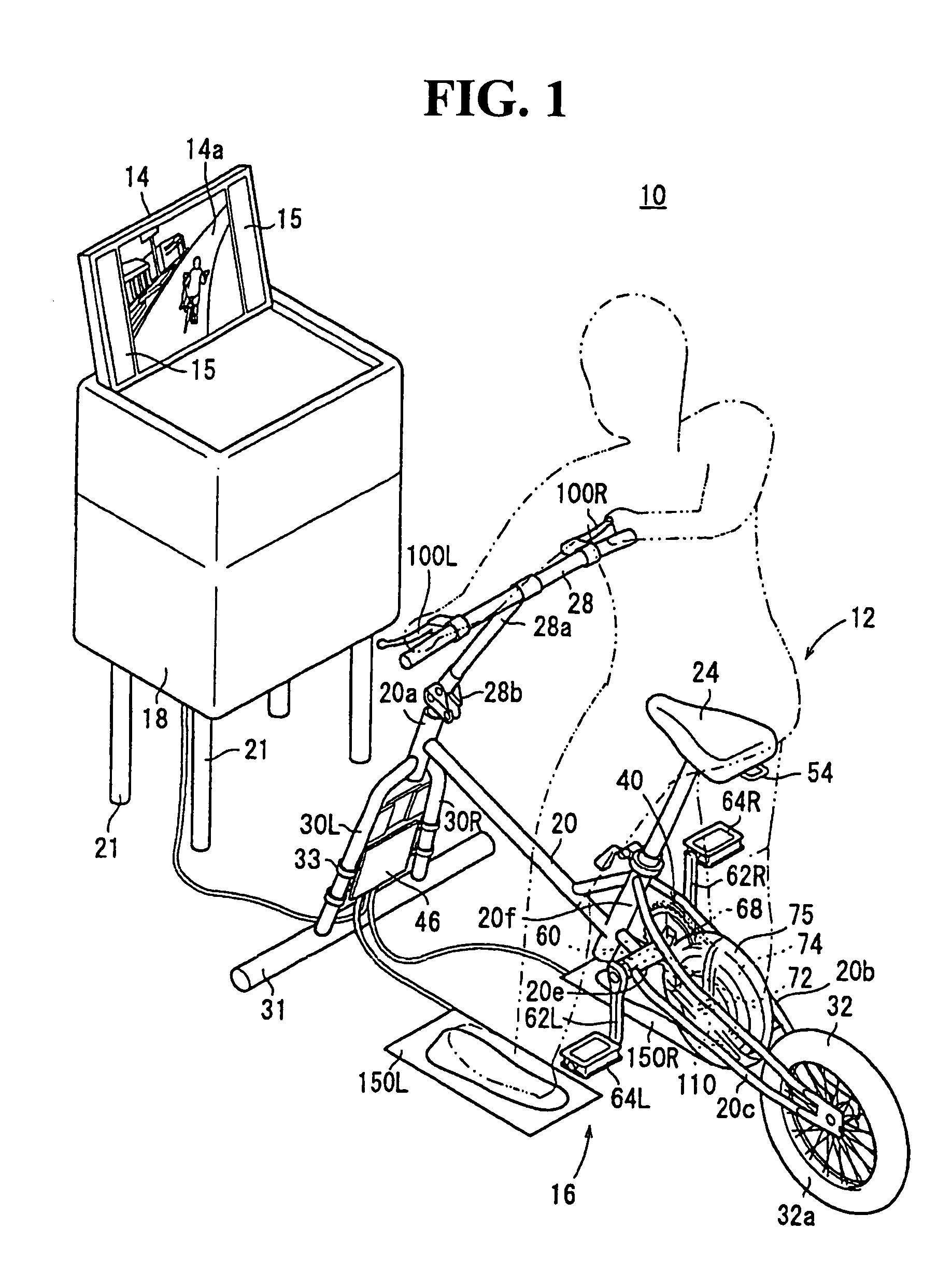
[0044]As shown in FIG. 1, the bicycle simulation system 10 according to this embodiment has a dummy bicycle 12, a monitor 14 for displaying scenery according to the operation of the dummy bicycle 12 on a screen 14a, a loudspeaker 15 for providing simulated sounds and vocal instructions to the rider, a mat switch 16 provided at a position where the rider rides on and gest off the dummy bicycle 12, and a main control unit 18 for performing total control of the bicycle simulation system 10. The main control unit 18 is disposed on the front side of the dummy bicycle 12. The monitor 14 and the loudspeaker 15 are disposed at an upper portion of the main control unit 18 and at positions permitting easy visual ...


PUM


Abstract

To realize a light steering handle operation similar to that of a real bicycle, and to obtain an appearance similar to that of a real bicycle. A bicycle simulation system has a turnable steering handle, a left-right pair of pedals, a frame for turnably supporting the steering handle and the pedals, a monitor for displaying a scenery according to the simulated running velocity required by a first speed pickup, a controller supplying sensor signals to a main control unit which controls the monitor. The controller is provided on front forks that function as a front stand.

Description

CROSS-REFERENCE TO RELATED APPLICATIONS[0001]This nonprovisional application claims priority under 35 U.S.C. § 119(a) on Patent Application Nos. 2005-157563 and 2005-187940, filed in Japan on May 30, 2005 and Jun. 28, 2005, respectively. The entirety of each of the above application is incorporated herein by reference.BACKGROUND OF THE INVENTION[0002]1. Field of the Invention:[0003]The present invention relates to a bicycle simulation system used for traffic safety education and training, games, physical training, or the like.[0004]2. Description of Background Art:[0005]Simulation systems corresponding to respective vehicles have been proposed for simulated experience of operations of an airplane, an automobile, a motorcycle, a bicycle and the like. Some of the simulation systems have been put to practical use. In a bicycle simulation system, a rider seated astride a saddle of a dummy bicycle works the pedals to thereby perform a simulated cycling. The rotation of the pedals is dete...

Claims


Application Information

Patent Timeline
Patent Type & Authority Patents(United States)
IPC IPC(8): A63B22/06A63B71/00
CPCA63B21/157A63B21/225A63B24/00A63B71/0622G09B19/0038A63B22/0605A63B2210/50A63B2220/16A63B2220/30
Inventor YONEHANA, ATSUSHIHANAYA, RYUKOUICHIMI, SADANAOMIYAMARU, YUKIO
Owner HONDA MOTOR CO LTD
Learn More