Tension maintaining structure, tension maintaining device and vibrating wire type equipment

A holding device and pulling force technology, applied in the field of pulling force holding device, pulling force holding structure, and vibrating wire equipment, can solve the problems of small pulling force and small actual pulling force, and achieve stable pulling force, improve stability, Easy-to-fit effect

Active Publication Date: 2021-07-09
厦门邦创信息技术有限公司
View PDF15 Cites 0 Cited by
  • Summary
  • Abstract
  • Description
  • Claims
  • Application Information

AI Technical Summary

Problems solved by technology

However, during the installation process of the existing tension-holding device for the tension in the cavity, after the installation is completed, the tension of the tension often becomes smaller, resulting in the actual tension of the tension being less than the set value

Method used


Image

  • Tension maintaining structure, tension maintaining device and vibrating wire type equipment
  • Tension maintaining structure, tension maintaining device and vibrating wire type equipment
  • Tension maintaining structure, tension maintaining device and vibrating wire type equipment

Examples


Embodiment 1

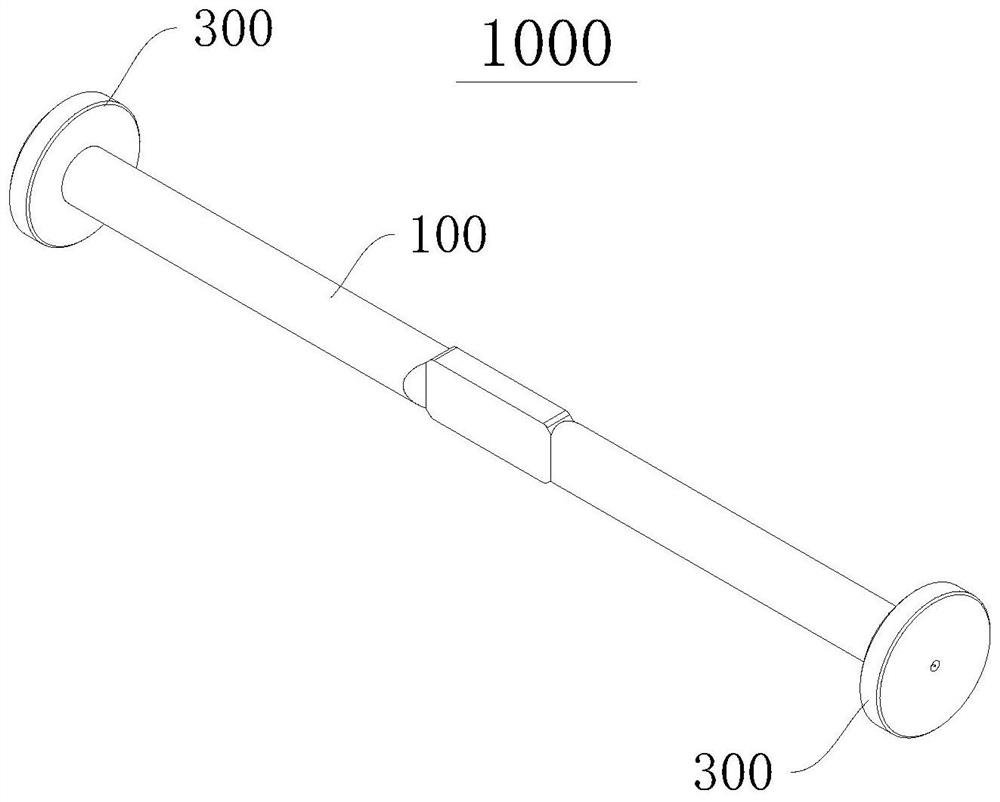
[0061] Please refer to figure 1 and figure 2 , the present embodiment provides a tension maintaining device 1000, suitable for vibrating wire equipment, tension piles, etc., which can keep the tension of the tension string 200 passing through the equipment in the above equipment stable.

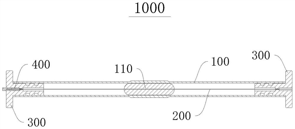
[0062] The tension holding device 1000 includes: a protective cover 100 , a base 300 and a fixing assembly 400 . Both ends of the protective cover 100 are equipped with a base 300 , and the pull string 200 can be accommodated in the protective cover 100 and passed through the base 300 . The fixing component 400 fixes the stay string 200 to the base 300 so that the tension of the stay string 200 remains constant.

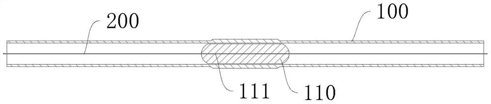
[0063] Please refer to image 3 , the protective sheath 100 is cylindrical as a whole, and the inner cavity of the protective sheath 100 is a hollow pipe passing through the protective sheath 100 along the axial direction. The stay string 200 is accommodated in the inner cavity...

Embodiment 2

[0116] Please refer to Figure 16 , and combined with Figure 15 , the present embodiment provides a vibrating wire device 2000 , the vibrating wire device 2000 includes a pulling string 200 , electromagnetic components (not shown in the figure) and a tension maintaining device 1000 .

[0117] The pull string 200 of the vibrating string device 2000 is fixed by a tension holding device 1000, the pull string 200 is arranged in the protective cover 100, and the two ends of the pull string 200 extend into the extension section 320 and the seat body 310 respectively, and are connected by the connecting piece 410 and stiffener 420 are fixed.

[0118] The electromagnetic components are installed in the hollow pipe of the protective cover to detect the change of the vibration frequency of the string 200 .

[0119] The vibrating wire device 2000 uses the tension holding device 1000 to fix the tension string, and the tension of the tension string remains unchanged at the initial prese...

Embodiment 3

[0122] Please refer to Figure 17 , this embodiment provides a tension holding structure 3000 , the tension holding structure 3000 includes the base 300 , the connecting piece 410 and the reinforcing piece 420 of the tension holding device 1000 in the first embodiment.

[0123] The base 300 can be used to connect with other objects, such as being installed on a concrete pile. In this way, by cooperating the base 300 and the fixing assembly 400, one end of the stay string 200 can be fixed, and the other end of the stay string 200 can be fixed. It can be used to connect with other objects that need to be subjected to tension, and the tension holding structure 3000 can continuously provide stable tension to other objects.

[0124] The tension maintaining structure 3000 can be applied to tighten and reinforce electric piles, and can be used to tension electric wires, but is not limited thereto.

[0125] Please refer to Figure 18 , in a modification of this embodiment, the shape...


PUM


Abstract

The invention discloses a tension holding structure, a tension holding device and vibrating wire equipment and relates to the technical field of tension holding. The tension maintaining structure comprises a base, a connecting piece and a reinforcing piece, wherein a through hollow channel is formed in the base, and a stop part is arranged in the hollow channel; the connecting piece is accommodated in the hollow channel; the reinforcing piece is contained in the hollow channel and is in interference fit with the connecting piece so that the connecting piece can abut against the stopping part; the tension holding device and the vibrating wire type equipment respectively comprise a tension holding structure. The structure is advantaged in that a technical problem that in the prior art, after an intra-cavity string pulling force maintaining device is installed, the pulling force of string pulling becomes small can be solved, after installation is completed, the pulling force of string pulling does not change, and a set value can be maintained.

Description

【Technical field】 [0001] The invention relates to the technical field of tension retention, in particular to a tension retention structure, a tension retention device and a vibrating wire device. 【Background technique】 [0002] When installing the pulling force holding device of the pulling string in the cavity, it is necessary to use a tension meter to accurately control the pulling force of the pulling string. the corresponding pull. However, during the installation process of the existing device for keeping the pulling force of the staying string in the cavity, after the installation is completed, the pulling force of the staying string often becomes smaller, resulting in that the actual pulling force of the staying string is smaller than the set value. [0003] In view of this, this application is proposed. 【Content of invention】 [0004] In order to solve the technical problem of the tension holding device in the cavity in the prior art that the tension of the strin...

Claims


Application Information

Patent Timeline
Patent Type & Authority Applications(China)
IPC IPC(8): G01H11/00G01H13/00
CPCG01H11/00G01H13/00
Inventor 徐廷端
Owner 厦门邦创信息技术有限公司
Why Eureka
Try Eureka