
Shot blasting auxiliary mechanism and shot blasting machine with same

An auxiliary mechanism and shot blasting machine technology, which is applied in the direction of manufacturing tools, abrasive jetting machine tools, used abrasive processing devices, etc., to achieve the effects of reducing friction, smooth rotation, and prolonging service life

Active Publication Date: 2021-07-13
南京汇恒机电有限公司
View PDF5 Cites 2 Cited by
  • Summary
  • Abstract
  • Description
  • Claims
  • Application Information

AI Technical Summary

Problems solved by technology

[0004] The invention aims to solve the technical problem of cleaning blind spots when selecting a rotary table shot blasting machine for cleaning or strengthening spherical workpieces

Method used


Image

  • Shot blasting auxiliary mechanism and shot blasting machine with same
  • Shot blasting auxiliary mechanism and shot blasting machine with same
  • Shot blasting auxiliary mechanism and shot blasting machine with same

Examples


Embodiment 1

[0040] Before describing this embodiment in detail, first introduce the application scenario of the present invention. The present invention is conceived based on the technical problem of cleaning blind spots in the existing rotary table shot blasting machine when cleaning round workpieces, and is mainly used in the field of shot blasting machines, but it does not exclude the application of the technical solution of the invention to other technical fields possibility.

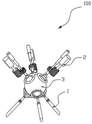
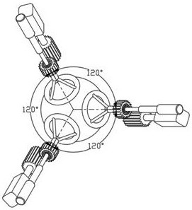
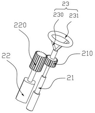
[0041] This embodiment will be described in detail below, according to Figure 1-Figure 8 As shown, a shot blasting auxiliary mechanism 100 according to the present application is used to assist the shot blasting of a spherical workpiece 3 , including: a support 1 for supporting the workpiece 3 and a driving assembly 2 for driving the workpiece 3 .

[0042] see figure 1, the support 1 surrounds the workpiece 3, and the spherical workpiece 3 can rotate in the space surrounded by the support 1; the drive assemb...

Embodiment 2

[0063] like Figure 1-Figure 9 As shown, a shot blasting machine 500 of the present application includes the shot blasting auxiliary mechanism 100 in Embodiment 1, the conical shot blasting chamber 5 and the shot blasting device 51 arranged in the shot blasting chamber 5 . The shot blasting machine 500 can realize 360° cleaning or strengthening of the spherical workpiece 3, eliminates the cleaning blind area caused by clamping, has a reasonable structure, and is easy to implement. The common parts of the prior art and this embodiment will not be repeated here. .

[0064] Wherein, the conical shot blasting chamber 5 can make the shot blasting collect by itself under the action of gravity, and the collection efficiency is high and easy to realize.

[0065] In addition, in order to ensure the effect of shot blasting, a plurality of shot blasting devices can be set in the shot blasting chamber 5, for example, three and three groups of shot blasting devices 51 coaxial with the dri...


PUM


Abstract

The invention provides a shot blasting auxiliary mechanism and a shot blasting machine with the shot blasting auxiliary mechanism, which are used for assisting shot blasting of a spherical workpiece. The shot blasting auxiliary mechanism comprises a supporting piece, the supporting piece surrounds a part of the spherical workpiece, and the spherical workpiece can rotate in a space defined by the supporting piece; driving components comprising a linear driving device and a rotary driving device, and at least three groups of driving components are uniformly distributed in the circumferential direction; and the rotary driving device comprises a driving gear, the driving gear is meshed with a driven gear, and the rotary driving device is used for driving the driving gear to rotate, so that the spherical workpiece rotates along with a friction piece. A part of the spherical workpiece is surrounded by the supporting piece, and the spherical workpiece is sequentially driven by the three groups of driving devices which are uniformly distributed in the circumferential direction, so that all surfaces of the spherical workpiece can be treated, and the problem of cleaning blind areas is solved.

Description

technical field [0001] The invention relates to the field of casting equipment, in particular to a shot blasting auxiliary mechanism and a shot blasting machine with the same. Background technique [0002] Shot blasting machine refers to casting equipment that uses high-speed projectiles thrown by a shot blaster to clean or strengthen the surface of a workpiece. At present, there are many types of shot blasting machines on the market, such as: rotary table type, chain plate type, drum type, hanging type and so on. [0003] When the workpiece is spherical, the drum type or the rotary table type is generally used. During the working process of the drum type shot blasting machine, the spherical workpiece will rotate and collide with the drum, which is only suitable for workpieces with lower surface requirements; if the rotary table type shot blasting machine is used, usually Use suction cups or similar fixtures to achieve clamping, which will result in a blind area for cleanin...

Claims


Application Information

Patent Timeline
Patent Type & Authority Applications(China)
IPC IPC(8): B24C3/04B24C9/00
CPCB24C3/04B24C9/00
Inventor 李小凡李慧媛何佳昊姚金泽
Owner 南京汇恒机电有限公司
Learn More