
Positioning module and unmanned aerial vehicle patrol system thereof

A positioning module and positioning plate technology, which is applied to unmanned aerial vehicles, motor vehicles, aircraft parts, etc., can solve the problems of increasing subjective judgment errors, increasing manpower input, and being unfavorable for use in particularly remote areas, and achieving a simple structure. , the effect of reducing labor costs and reducing the error range

Inactive Publication Date: 2021-07-13
CHONGQING WANCHONGSHAN INTELLIGENT TECH CO LTD
View PDF0 Cites 0 Cited by
  • Summary
  • Abstract
  • Description
  • Claims
  • Application Information

AI Technical Summary

Problems solved by technology

However, it is absolutely dependent on inspectors, so it is not conducive to use in particularly remote areas
[0003] In some special inspection areas, such as mine inspections and mountain forest inspections, due to their remoteness, there are still many changes in the way of using manual inspection drones for inspections, such as how to overcome survival problems and how to charge inspection drones battery life, how to reduce dependence on operators, etc.
Once the above problems cannot be solved, it will inevitably lead to the need to manually operate the inspection drone to conduct inspections, which will not only greatly increase manpower investment, but also increase the risk of subjective judgment errors

Method used


Image

  • Positioning module and unmanned aerial vehicle patrol system thereof
  • Positioning module and unmanned aerial vehicle patrol system thereof
  • Positioning module and unmanned aerial vehicle patrol system thereof

Examples


Embodiment Construction

[0024] The following will clearly and completely describe the technical solutions in the embodiments of the present invention with reference to the drawings in the embodiments of the present invention.

[0025] In describing the present invention, it should be understood that the terms "upper", "lower", "front", "rear", "left", "right", "top", "bottom", "inner", " The orientation or positional relationship indicated by "outside", etc. is based on the orientation or positional relationship shown in the drawings, and is only for the convenience of describing the present invention and simplifying the description, rather than indicating or implying that the referred device or element must have a specific orientation, so as to Specific orientation configurations and operations, therefore, are not to be construed as limitations on the invention.

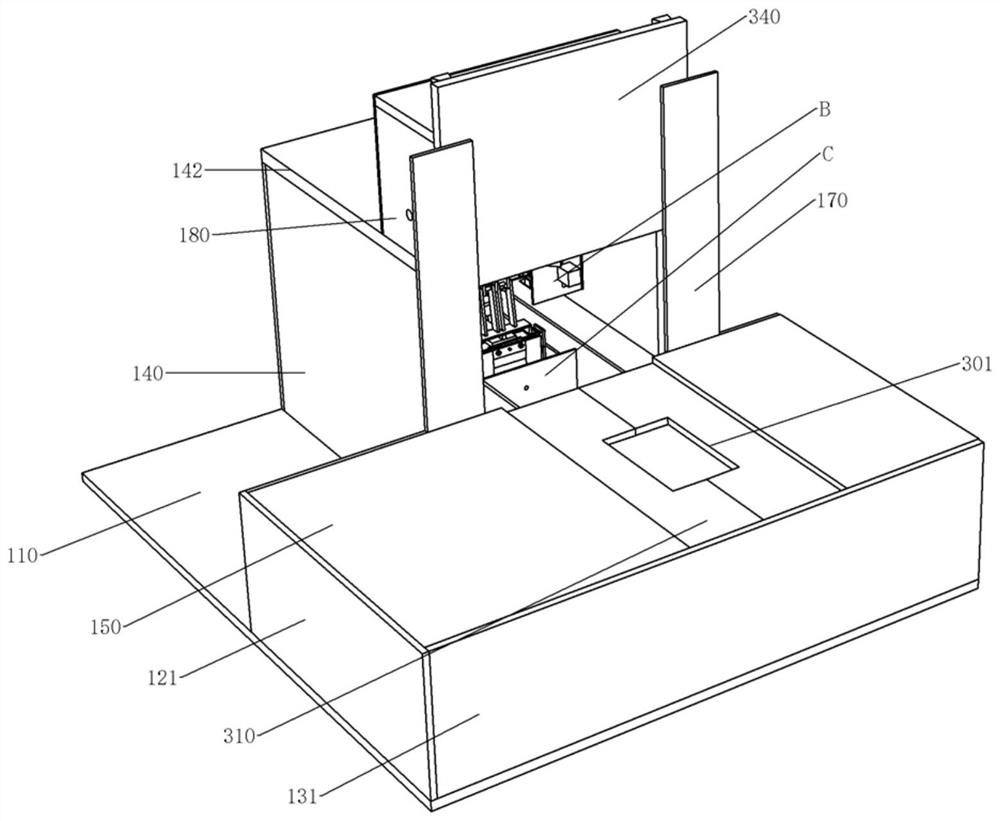
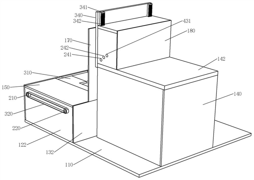
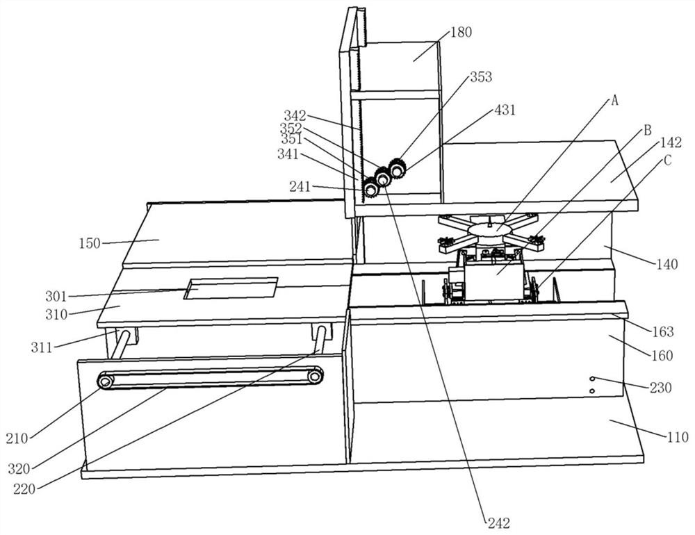
[0026] see Figure 1-Figure 39 , the unmanned aerial vehicle patrol system of the present embodiment, comprises:

[0027] The inspectio...


PUM


Abstract

The invention discloses a positioning module and an unmanned aerial vehicle patrol system thereof. The positioning module comprises a positioning plate, an end part positioning plate and a side end positioning plate, the end positioning plates and the end power plates are in direct or indirect dynamic assembly, the end power plates are arranged on the power screw in a sleeving mode and assembled with the power screw in a screwed mode through threads, the threads, screwed with the power screw, of the two end power plates are opposite, and the power screw is assembled with the positioning side plates at the two ends of the power screw. The bottom of the end power plate is mounted on the positioning frame; two first positioning frame vertical plates, two second positioning frame vertical plates and two third positioning frame vertical plates are respectively mounted on the positioning frame; the first positioning frame vertical plate and the second positioning frame vertical plate on the same side are respectively assembled with a lateral moving screw rod, a lateral end power plate is arranged between the first positioning frame vertical plate and the second positioning frame vertical plate on the same side, the lateral moving screw rod penetrates through the lateral end power plate and is assembled with the lateral end power plate through threads in a screwing manner, and the lateral moving screw rod is driven by a power screw rod; and the side end positioning plate and the side end power plate are directly or indirectly assembled.

Description

technical field [0001] The invention relates to an inspection drone and inspection technology of the inspection drone, in particular to an inspection drone, a fully automatic hangar and an inspection system for the drone. Background technique [0002] Inspection drones are a technology that has emerged and matured in recent years. At present, inspection drones can be used to achieve various tasks, and inspections are no exception. In the field inspection mission, at present, the operator mainly uses the inspection drone to reach the inspection range and then uses the inspection drone to fly for inspection. This method can greatly increase the inspection efficiency, and also reduces the labor intensity of the inspectors. However, it is absolutely dependent on inspectors, so it is not conducive to use in particularly remote areas. [0003] In some special inspection areas, such as mine inspections and mountain forest inspections, due to their remoteness, there are still many...

Claims


Application Information

Patent Timeline
IPC IPC(8): B60L53/12B60L53/14B60L53/30B64C25/34B64C39/02B64F1/00
CPCB64C39/02B64C25/34B64F1/007B60L53/30B60L53/12B60L53/14B60L2200/10B64U2101/00Y02T10/70Y02T10/7072Y02T90/12Y02T90/14
Inventor 李天琼
Owner CHONGQING WANCHONGSHAN INTELLIGENT TECH CO LTD
Learn More