3D holographic display rotor wing and working method thereof

A holographic display and rotor technology, which is applied in the direction of rotorcraft, lighting and heating equipment, instruments, etc., can solve the problems of narrow application areas, and achieve the effects of quality assurance, good economy, and good economy

Pending Publication Date: 2021-07-13
NANJING INTELLIGENT BIG DRONE INST OF TECH LTD
View PDF0 Cites 0 Cited by
  • Summary
  • Abstract
  • Description
  • Claims
  • Application Information

AI Technical Summary

Problems solved by technology

Narrow application

Method used


Image

  • 3D holographic display rotor wing and working method thereof
  • 3D holographic display rotor wing and working method thereof
  • 3D holographic display rotor wing and working method thereof

Examples


Embodiment Construction

[0031] The present invention will be further described below in conjunction with accompanying drawing.

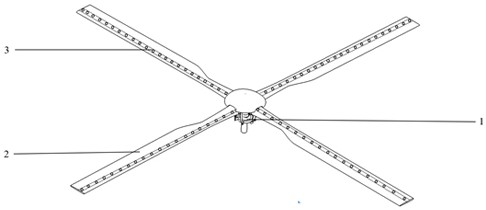
[0032] A 3D holographic display rotor of the present invention includes: a rotor hub 1 , a rotor blade 2 and an RGB LED light strip 3 .

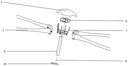
[0033] Described rotor hub 1 is as shown in the figure and figure 2 As shown, it includes: rotor hub fairing 5 , control integration module 6 , automatic tilter 7 , rotor shaft 8 , signal and power wire 9 , and power supply and signal module 10 . The rotor hub fairing is fixed at the root of the blade, and is fixedly connected with the root of the blade and the rotor shaft by bolts. The control integrated module 6 is fixed on the upper end of the rotor shaft 8, in the middle of the automatic tilter 7 and the rotor hub fairing 5, and its function is to convert the high voltage in the aircraft into a low voltage (such as 12V or 24V) for RGB LED The light strip is powered, and the second is to convert the video or picture signal into an e...


PUM


Abstract

The invention provides a 3D holographic display rotor wing and a working method thereof. The rotor wing comprises a rotor wing propeller hub, rotor wing blades and RGB LED lamp strips. The rotor wing propeller hub comprises a rotor wing propeller hub fairing, a control integration module, an automatic inclinator, a rotor wing shaft, a signal and power supply wire and a power supply and signal module. The rotor wing blade comprises a front edge counterweight, a C-shaped girder, a skin, a foam core, a rear edge strip and a lamp strip mounting groove, and the lamp strip mounting groove is a cross rectangular mounting groove formed in the C-shaped girder; the RGB LED lamp strip comprises a lamp strip shell and RGB LED lamp beads, the lamp strip shell is in a cross rectangular shape and is used in cooperation with the lamp strip mounting groove, and the lamp strip is mounted and dismounted in an insertion and extraction mode. The 3D holographic display rotor wing is easy to disassemble and assemble, high in cost performance, capable of displaying advertisements such as video images in the air and capable of being used as the air traffic signal lamp by displaying three colors of red, yellow and green, and wide in application prospect.

Description

technical field [0001] The invention relates to the technical field of aviation equipment, in particular to a 3D holographic display rotor and a working method thereof. Background technique [0002] In recent years, various rotorcrafts have been greatly developed, and both helicopters and flying cars are coming into the public's field of vision. 3D holographic display is a device made of the principle that the visual effect produced by light on the retina will remain for a short period of time after the light stops acting. When the device is imaging, it is all LED lights, and the surrounding rotor surface is dark. And if there is no light, then when the rotor rotates, the human eye will only receive the stay of light, and the dark and dull ones will be too fast to be distinguished by the brain, so the display effect will only stay on the light displayed by the LED. In this way, the effect of aerial imaging is realized; then, when the human eyes observe space objects, becaus...

Claims


Application Information

Patent Timeline
Patent Type & Authority Applications(China)
IPC IPC(8): B64C27/32B64C27/46F21V19/00G09F9/33F21Y115/10
CPCB64C27/32B64C27/46F21V19/001F21Y2115/10G09F9/33
Inventor 刘佳李小光朱清华
Owner NANJING INTELLIGENT BIG DRONE INST OF TECH LTD
Why Eureka
Try Eureka