Supercharge Your Innovation With Domain-Expert AI Agents!

Safety pliers that adjust by instantaneous reduction in self -adjustment

An average deceleration and self-adjusting technology, applied in the field of safety gear, can solve the problems of inability to average deceleration, achieve the effect of reducing friction and ensuring stability

Active Publication Date: 2022-03-01
南通中力科技有限公司
View PDF8 Cites 0 Cited by
  • Summary
  • Abstract
  • Description
  • Claims
  • Application Information

AI Technical Summary

Problems solved by technology

[0004] The purpose of the present invention is to solve the shortcoming that the existing elevator cannot perform average deceleration safely, quickly and effectively when the speed is too fast, and proposes a self-adjusting safety gear through instantaneous average deceleration

Method used


Image

  • Safety pliers that adjust by instantaneous reduction in self -adjustment
  • Safety pliers that adjust by instantaneous reduction in self -adjustment
  • Safety pliers that adjust by instantaneous reduction in self -adjustment

Examples


Embodiment 1

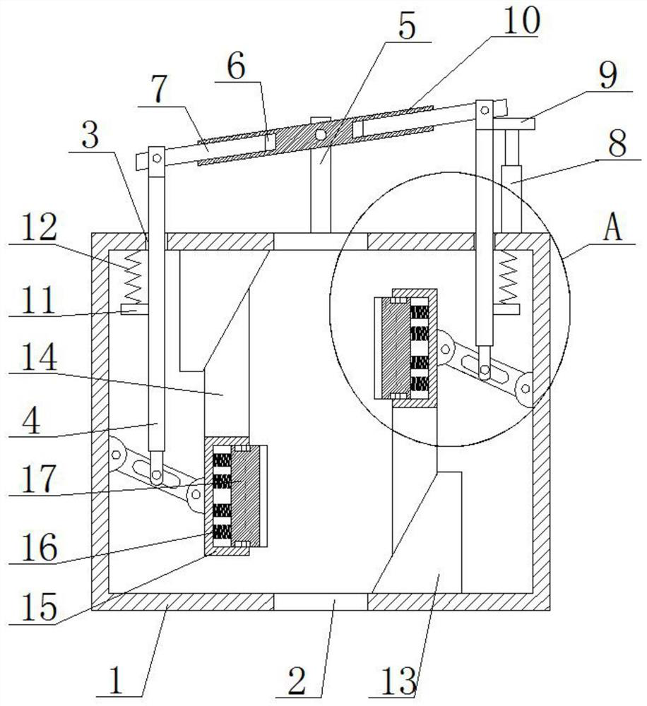
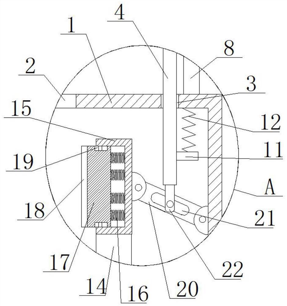
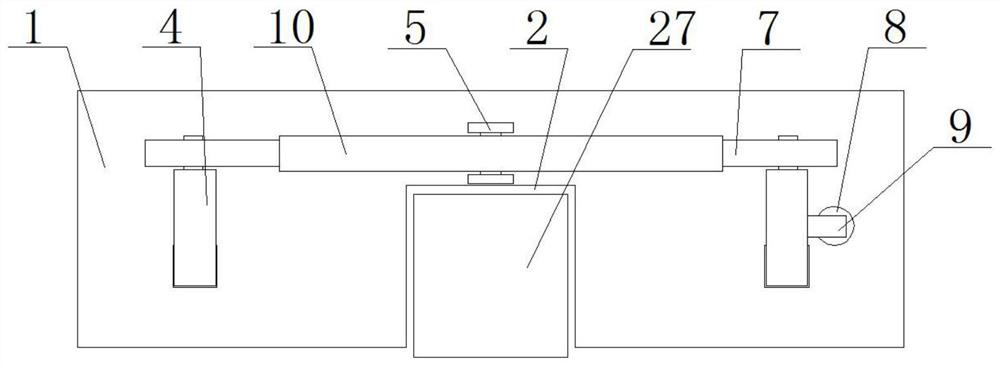
[0030] refer to Figure 1-5 , the self-adjusting safety gear through instantaneous average deceleration, including a frame box 1, a guide rail notch 2 is opened on the front of the frame box 1, a guide rail 27 is movably connected in the guide rail notch 2, and two sliding holes 3 are opened on the top of the frame box 1 , the two sliding holes 3 are slidingly installed with a pull rod 4, and the bottoms of the two pull rods 4 are movably connected with a lever mechanism, and the two lever mechanisms are misplaced. Friction deceleration mechanism and guide mechanism, the guide mechanism is connected with the inner wall of the frame box 1, the top of the frame box 1 is provided with a lever unit, the lever unit is connected with two pull rods 4 in rotation, and the top of the frame box 1 is provided with a push rod cylinder 8, which pushes The output shaft of the rod cylinder 8 is connected with a connecting block 9, and the connecting block 9 is connected with one of the two p...

Embodiment 2

[0041] refer to Figure 1-5 , the self-adjusting safety gear through instantaneous average deceleration, including a frame box 1, a guide rail notch 2 is opened on the front of the frame box 1, a guide rail 27 is movably connected in the guide rail notch 2, and two sliding holes 3 are opened on the top of the frame box 1 , the two sliding holes 3 are slidingly installed with a pull rod 4, and the bottoms of the two pull rods 4 are movably connected with a lever mechanism, and the two lever mechanisms are misplaced. Friction deceleration mechanism and guide mechanism, the guide mechanism is connected with the inner wall of the frame box 1, the top of the frame box 1 is provided with a lever unit, the lever unit is connected with two pull rods 4 in rotation, and the top of the frame box 1 is provided with a push rod cylinder 8, which pushes The output shaft of rod cylinder 8 is connected with connection block 9, and connection block 9 links to each other with a pull rod 4 in two...


PUM


Abstract

The invention belongs to the technical field of safety gear, especially the safety gear which can be adjusted by itself through the instantaneous average deceleration. Aiming at the problem that the existing elevator cannot perform average deceleration safely, quickly and effectively when the speed is too fast, the following proposal is now proposed. Including the frame box, the front of the frame box is provided with a guide rail gap, and the guide rail is movably connected to the guide rail gap, and the top of the frame box is opened with two slide holes, and the two slide holes are slidingly installed with pull rods, and the bottom of the two pull rods are movable. A lever mechanism is connected, and the two lever mechanisms are misplaced. A support seat is connected to the lever mechanism, and a friction deceleration mechanism and a guide mechanism are connected to the support seat. The guide mechanism is connected to the inner wall of the frame box, and the top of the frame box is provided with a lever unit. , the lever unit is rotatably connected with two pull rods, and a push rod cylinder is arranged on the top of the frame box. The invention can automatically decelerate evenly when the elevator speed is too fast.

Description

technical field [0001] The invention relates to the technical field of safety gear, in particular to a safety gear that can be self-adjusted through instantaneous average deceleration. Background technique [0002] The elevator safety gear device is under the control of the speed limiter. When the elevator speed exceeds the limit speed set by the elevator speed limiter, or when the suspension rope breaks and relaxes, it will stop the car in an emergency and clamp it on the guide rail. A safety device on the elevator, which provides effective protection for the safe operation of the elevator, and is generally installed on the car frame or counterweight frame. [0003] Existing elevators cannot perform average deceleration safely, quickly and effectively when the speed is too fast. Contents of the invention [0004] The purpose of the present invention is to solve the defect that the existing elevator cannot perform average deceleration safely, quickly and effectively when ...

Claims


Application Information

Patent Timeline
Patent Type & Authority Patents(China)
IPC IPC(8): B66B5/18B66D5/14B66D5/26F16F15/067
CPCB66B5/18B66D5/14B66D5/26F16F15/067
Inventor 金锋金桂勇张立民范伟张超刘琪巍邓小维
Owner 南通中力科技有限公司
Features
  • R&D
  • Intellectual Property
  • Life Sciences
  • Materials
  • Tech Scout
  • Unparalleled Data Quality
  • Higher Quality Content
  • 60% Fewer Hallucinations
Learn More