Implant delivery system and inner tube thereof

A technology for delivery systems and implants, applied in stents and other directions, can solve the problems of complicated and difficult release, large volume of the post-release mechanism, and easily unstable bending after release, so as to achieve no axial shortening, and improve the ease of implementation and performance. Practicality, release the effect of accurate positioning

Pending Publication Date: 2021-07-16
SHANGHAI VASOLUTIONS MEDTECH CO LTD
View PDF2 Cites 0 Cited by
  • Summary
  • Abstract
  • Description
  • Claims
  • Application Information

AI Technical Summary

Problems solved by technology

However, due to the large volume of the rear release mechanism itself, this method is generally only suitable for systems with a thicker outer tube diameter. In addition, because the inner tube bears a large axial compression force during the release process, it is prone to instability and bending during the release process.
[0006] Moreover, the above delivery system needs to operate multiple parts to release the stent. After the stent is released, an operating mechanism is required to release the rear release constraint at the far end, which has the disadvantage of complicated and difficult release.

Method used


Image

  • Implant delivery system and inner tube thereof
  • Implant delivery system and inner tube thereof
  • Implant delivery system and inner tube thereof

Examples


Embodiment 1

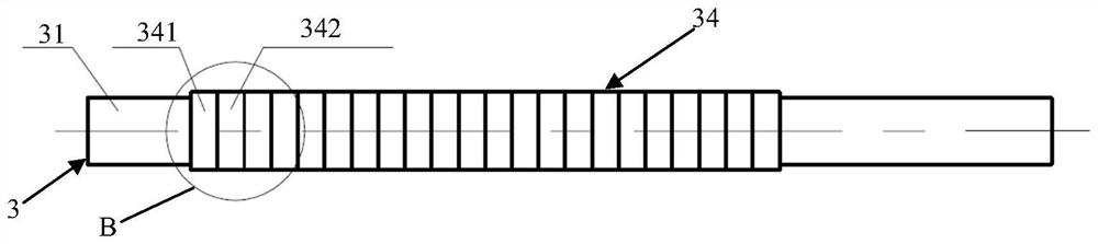
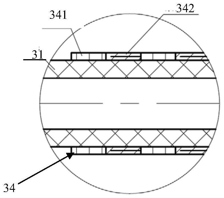
[0041] In this embodiment, the plurality of friction bodies 34 are distributed along the axial direction of the inner tube body 31 , and the first friction layers 341 and the second friction layers 342 are distributed alternately along the axial direction of the inner tube body 31 .

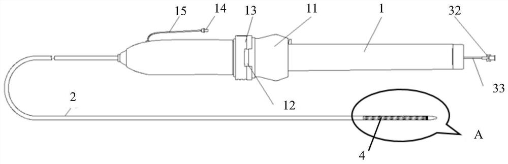
[0042] figure 2 for figure 1 Schematic diagram of the structure of the inner tube at A. See figure 2 , the inner tube 3 includes an inner tube main body 31, the outer surface of the distal end of the inner tube main body 31 is alternately provided with first friction layers 341 and second friction layers 342 in the axial direction, and the first friction layer 341 is composed of a friction layer having a first friction coefficient. The second friction layer 342 is made of a material with a second coefficient of friction. The material with the first coefficient of friction is a material with a high coefficient of friction, preferably silica gel or polyurethane; the material with the second co...

Embodiment 2

[0046] It is different from the alternate distribution of the first friction layer 341 and the second friction layer 342 in Embodiment 1. The friction body 34 of this embodiment includes the first friction layer 341 and the second friction layer 342 distributed along the radial direction of the inner pipe main body, and the first friction layer 341 is located on the inner pipe main body 31 and between the second friction layer 342 . See Image 6 , the friction layer 34 provided on the outer surface of the inner pipe body 31 at the place where the bracket 4 is placed has a first side 343 and a second side 344; the first side 343 has a first friction layer 341, and the second side 344 has a second friction layer 342 . When the friction body 34 is in the first state, the friction body 34 is folded in the axial direction of the inner tube main body 31, the first side 343 has a first surface 3431 and a second surface 3432, and at least the second surface 3432 of the first side 34...


PUM


Abstract

The invention discloses an implant delivery system and an inner tube thereof; the inner tube comprises an inner tube main body and a friction body arranged on the outer surface of the inner tube main body; the friction body comprises a first friction layer and a second friction layer with different friction coefficients; the friction body has a first state and a second state; when the friction body is in the first state, the first friction layer is exposed out of the outer surface of the inner pipe main body; and when the friction body is in the second state, the first friction layer is covered, and the second friction layer is exposed out of the outer surface of the inner pipe main body. According to the implant delivery system provided by the invention, an implant can be released and positioned accurately and stably; axial shortening is avoided; and meanwhile, safe withdrawing of the delivery system can be guaranteed.

Description

technical field [0001] The invention relates to the technical field of medical devices, in particular to an implant delivery system and an inner tube thereof. Background technique [0002] With the development of endoluminal technology, the use of stents has been widely recognized by radiologists, cardiologists and surgeons. Stents and stent grafts are used to support various tubular passages in the body, including arteries, veins, air tract, gastrointestinal tract, and bile ducts. The preferred method of placing a stent is to use a specialized delivery system through the body's natural pathways for precise placement and deployment at the intended treatment site. With the small outer diameter of the delivery system, physicians can minimize surgical incisions for minimally invasive procedures. [0003] Stents are generally plastically deformable (eg, "balloon-expandable" stents) or elastically deformable (eg, "self-expanding" stents) to return from a compressed state to a w...

Claims


Application Information

Patent Timeline
Patent Type & Authority Applications(China)
IPC IPC(8): A61F2/966A61F2/97
CPCA61F2/966A61F2/97
Inventor 朱清刘梦钦姬庆茹袁振宇
Owner SHANGHAI VASOLUTIONS MEDTECH CO LTD
Why Eureka
Try Eureka