Implant delivery system and inner tube thereof

A delivery system and implant technology, applied in the direction of stents, etc., can solve the problems of easily unstable bending, large volume of the post-release mechanism, complicated and difficult release, etc., so as to avoid the displacement of the implant, improve the ease of implementation and Practicality, release the effect of accurate positioning

Pending Publication Date: 2021-07-16
SHANGHAI VASOLUTIONS MEDTECH CO LTD
View PDF2 Cites 2 Cited by
  • Summary
  • Abstract
  • Description
  • Claims
  • Application Information

AI Technical Summary

Problems solved by technology

However, due to the large volume of the rear release mechanism itself, this method is generally only suitable for systems with a thicker outer tube diameter. In addition, because the inner tube bears a large axial compression force during the release process, it is prone to instability and bending during the release process.
[0006] Moreover, the above delivery system needs to operate multiple parts to release the stent. After the stent is released, an operating mechanism is required to release the rear release constraint at the far end, which has the disadvantage of complicated and difficult release.

Method used


Image

  • Implant delivery system and inner tube thereof
  • Implant delivery system and inner tube thereof
  • Implant delivery system and inner tube thereof

Examples


Embodiment Construction

[0035] The present invention will be further described below in conjunction with the accompanying drawings and embodiments.

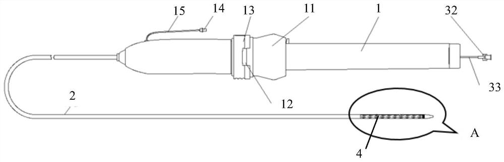
[0036] In order to describe the structural features of the present invention more clearly, the present invention adopts " near end ", " far end ", " axial " as location words, and wherein " near end " represents an end near the operator in the operation process; "End" means the end away from the operator, and the axial direction means the direction of the axis of the inner tube. The terms "inner", "outer", "upper", "lower", "left", "right" and similar expressions used in the present invention are for the purpose of illustration only and do not represent the only embodiment. The term "or" is generally used in its sense including "and / or" unless the content clearly dictates otherwise.

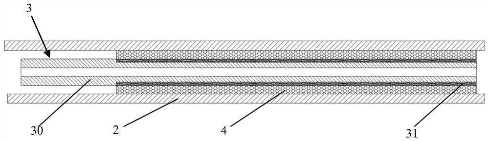
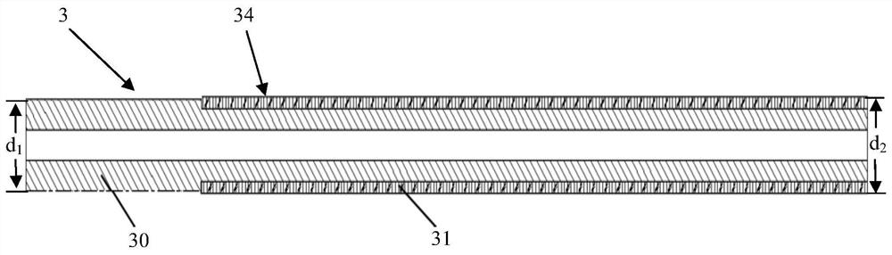
[0037] In order to solve the serious problem of stent shortening during the stent release process, one idea is to significantly increase the friction between the inner tu...


PUM

PropertyMeasurementUnit
Axial lengthaaaaaaaaaa

Abstract

The invention discloses an implant delivery system and an inner tube thereof; the implant delivery system comprises a handle, an outer tube and the inner tube; the outer tube and the inner tube are both connected with the handle; the handle controls the outer tube and the inner tube to move in the axial direction; the inner tube comprises an inner tube body and at least one protruding part located on the outer side of the inner tube body; each protruding part comprises a plurality of protruding single bodies; one ends of the protruding single bodies are connected with the inner tube body; and the other ends of the protruding single bodies extend towards the far end of the inner tube body. In the implant delivery system provided by the invention, the inner tube and an implant are unidirectionally occluded, so that a relatively large static friction force required by release of the implant is provided, and the release and positioning of the implant are accurate and stable without generating axial shortening; and meanwhile, the structure can effectively reduce the friction force between the inner tube and the implant when the inner tube retracts, so that the implant is prevented from being moved due to retraction of the delivery system, and the operation is safer.

Description

technical field [0001] The invention relates to the technical field of medical devices, in particular to an implant delivery system and an inner tube thereof. Background technique [0002] With the development of endoluminal technology, the use of stents has been widely recognized by radiologists, cardiologists and surgeons. Stents and stent grafts are used to support various tubular passages in the body, including arteries, veins, air tract, gastrointestinal tract, and bile ducts. The preferred method of placing a stent is to use a specialized delivery system through the body's natural pathways for precise placement and deployment at the intended treatment site. With the help of the small outer diameter of the delivery system, doctors can minimize surgical incisions to achieve minimally invasive procedures. [0003] Stents are typically plastically deformable (eg, "balloon-expandable" stents) or elastically deformable (eg, "self-expanding" stents) to return from a compres...

Claims


Application Information

Patent Timeline
IPC IPC(8): A61F2/966
CPCA61F2/966
Inventor 朱清刘梦钦姬庆茹袁振宇
Owner SHANGHAI VASOLUTIONS MEDTECH CO LTD
Why Eureka
Try Eureka