
Efficient wood peeling machine with cutting mechanism

A technology of cutting mechanism and peeling machine, which is applied in the direction of wood processing equipment, bark, manufacturing tools, etc. It can solve the problems of not being able to clamp and fix the wood, easy to damage the wood, and low peeling quality, so as to ensure the peeling effect and avoid damage to the wood , The effect of saving equipment resources

Inactive Publication Date: 2021-07-16
合创博远(北京)科技有限公司
View PDF0 Cites 2 Cited by
  • Summary
  • Abstract
  • Description
  • Claims
  • Application Information

AI Technical Summary

Problems solved by technology

[0002] The wood needs to be removed by a wood peeling machine before processing. The length of the wood that can be processed by the existing wood peeling machine is certain, and the wood of different lengths cannot be clamped and fixed; in the process of peeling the wood Easy to damage wood, low peeling quality

Method used


Image

  • Efficient wood peeling machine with cutting mechanism
  • Efficient wood peeling machine with cutting mechanism
  • Efficient wood peeling machine with cutting mechanism

Examples


Embodiment 1

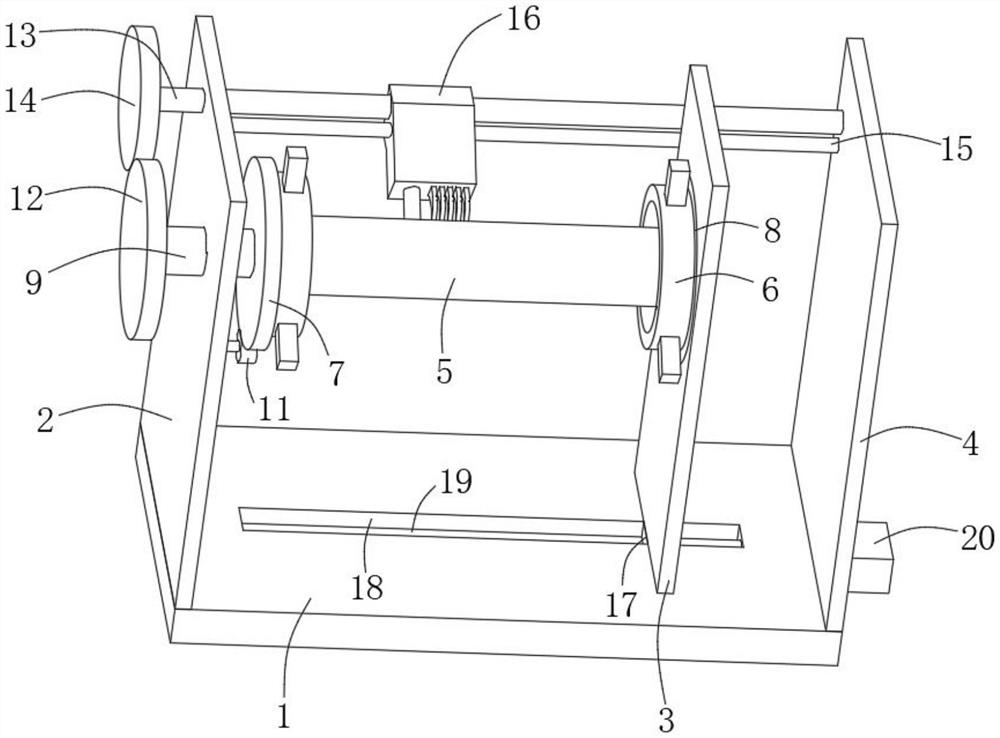
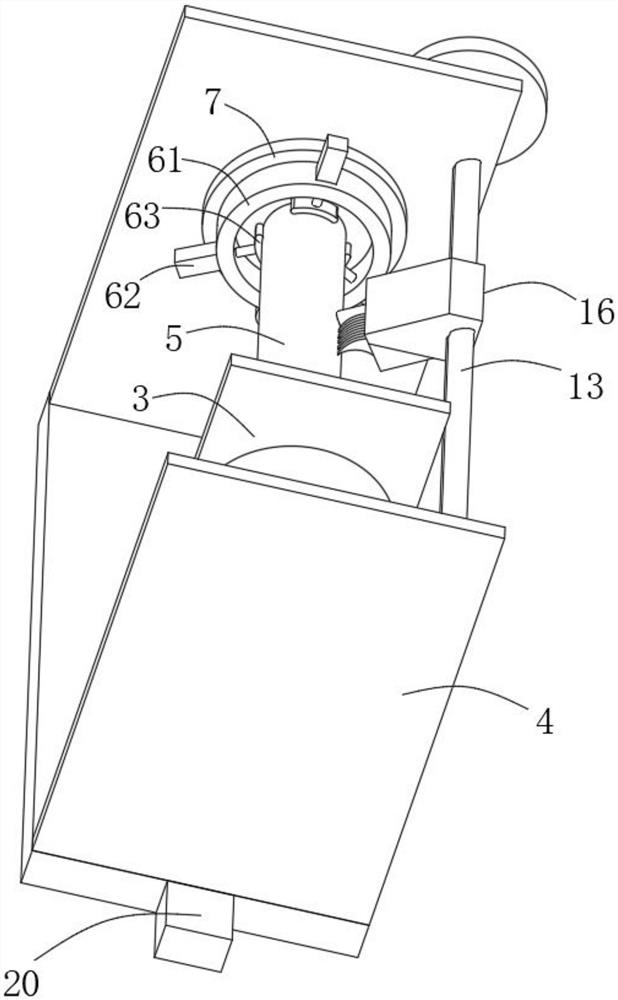
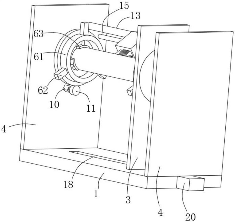
[0025] refer to Figure 1-5 , a high-efficiency wood peeling machine provided with a cutting mechanism, comprising a bottom plate 1, the upper end of the bottom plate 1 is symmetrically fixedly connected with a first support plate 2 and a second support plate 4, between the first support plate 2 and the second support plate 4 A clamping plate 3 is arranged in parallel, the width of the first support plate 2 and the second support plate 4 are equal, the width of the clamping plate 3 is smaller than the width of the first support plate 2, and the first threaded rod 13 and the guide rod 15 are located at On one side of the clamping plate 3 , the clamping plate 3 will not interfere with the rotation of the first threaded rod 13 .

[0026] An axial displacement device is connected between the clamping plate 3 and the base plate 1. Specifically, the axial displacement device includes a slider 17 fixed on the lower end of the clamping plate 3. The upper end of the base plate 1 is pro...

Embodiment 2

[0035] In this embodiment, the following improvements are made on the basis of Embodiment 1: one end of the rotating rod 9 passes through the third gear 12 and is coaxially fixedly connected with a cutting knife.

[0036] In the process of peeling the wood 5 to be peeled, in order to save power, the rotating rod 9 can cut other woods in the process of driving the cutting knife to rotate, so as to prepare for the next peeling and improve the efficiency of cutting and peeling.


PUM


Abstract

The invention discloses an efficient wood peeling machine with a cutting mechanism. The efficient wood peeling machine comprises a bottom plate, a first supporting plate and a second supporting plate are symmetrically and fixedly connected to the upper end of the bottom plate, a clamping plate is arranged between the first supporting plate and the second supporting plate in parallel, an axial displacement device is connected between the clamping plate and the bottom plate, the first supporting plate and the clamping plate are rotationally connected with a rotating rod and a circular plate correspondingly, the axis of the rotating rod coincides with the axis of the circular plate, the two ends of the rotating rod are coaxially and fixedly connected with a third gear and a first gear correspondingly, wood clamps are mounted on the opposite sides of the first gear and the circular plate correspondingly, to-be-peeled wood is jointly clamped between the two wood clamps, and a first motor is fixedly mounted on the side, facing the clamping plate, of the first supporting plate. Different types of to-be-peeled wood can be clamped, and the peeling quality is guaranteed under the condition that equipment resources are limited.

Description

technical field [0001] The invention relates to the technical field of wood peeling, in particular to a high-efficiency wood peeling machine provided with a cutting mechanism. Background technique [0002] The wood needs to be removed by a wood peeling machine before processing. The length of the wood that can be processed by the existing wood peeling machine is certain, and the wood of different lengths cannot be clamped and fixed; in the process of peeling the wood It is easy to damage the wood and the peeling quality is low. [0003] For this reason, we propose a kind of efficient timber peeling machine that is provided with cutting mechanism to solve the above problems. Contents of the invention [0004] The present invention intends to provide a high-efficiency wood peeling machine provided with a cutting mechanism, which can clamp wood of different lengths and peel the wood without damaging the wood. [0005] In order to achieve the above object, the present invent...

Claims


Application Information

Patent Timeline
IPC IPC(8): B27L1/00
CPCB27L1/005
Inventor 赵光荣
Owner 合创博远(北京)科技有限公司
Learn More