Flange pipeline butt joint design method and system

A design method and design system technology, applied in computing, computer parts, image data processing, etc., can solve the problems of low information utilization, inconvenient mold operation, long design cycle, etc., to improve design accuracy and reduce life safety. Risks and equipment safety risks, the effect of improving the utilization of spatial information

Pending Publication Date: 2020-11-10
WUHAN INSTITUTE OF TECHNOLOGY +1
View PDF3 Cites 1 Cited by
  • Summary
  • Abstract
  • Description
  • Claims
  • Application Information

AI Technical Summary

Problems solved by technology

[0004] The technical problem solved by the present invention is to provide a method and system for butt joint design of flanged pipes, which solves the problems of inconvenient profiling, low information utilization, low precision, and long design cycle in the process of pipeline butt joint design

Method used


Image

  • Flange pipeline butt joint design method and system
  • Flange pipeline butt joint design method and system
  • Flange pipeline butt joint design method and system

Examples


Embodiment Construction

[0033] The method and system for butt joint design of flanged pipes of the present invention will be further described below in conjunction with the accompanying drawings:

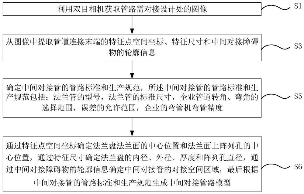
[0034] The flange pipe pipeline butt joint design method of the embodiment of the present invention, such as figure 1 shown, including the following steps:

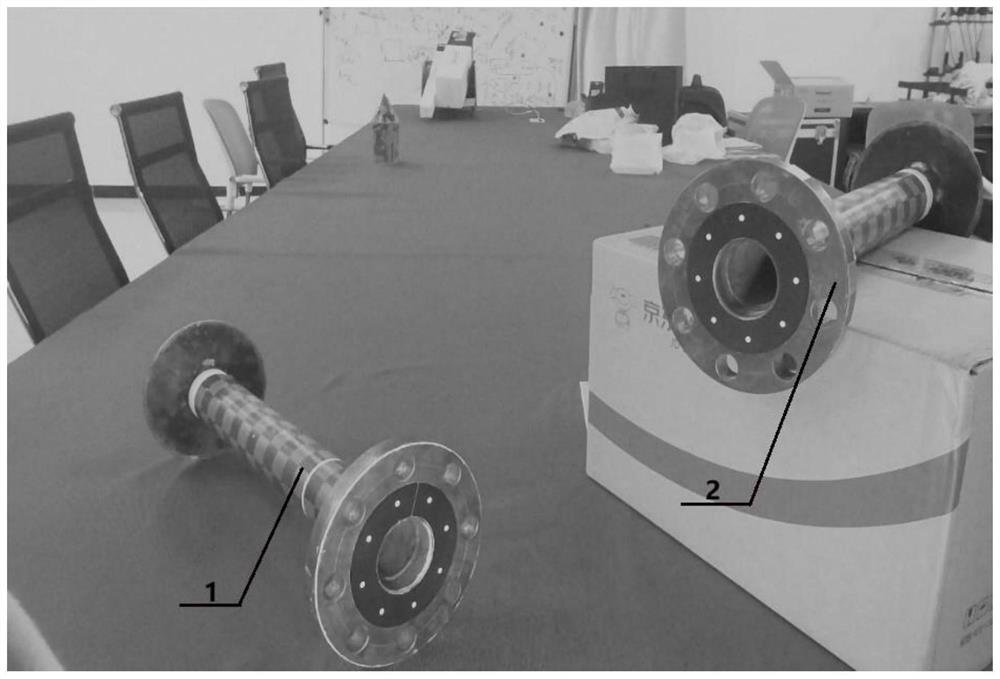
[0035] S1. Use the binocular camera to obtain the image of the place where the pipeline needs to be connected to the design. Such as figure 2 As shown, the binocular camera is used to take pictures of the design where the pipeline needs to be connected, mainly to take pictures of the connecting ends of the first sampling tube 1 and the second sampling tube 2, and then obtain the local image of the binocular camera. In order to improve the accuracy of the design, after the image is acquired, it can be manually or automatically screened through the human-computer interaction interface to obtain a better quality image.

[0036] S3. Extracting from th...


PUM


Abstract

The invention discloses a flange pipeline butt joint design method and system. The method comprises the steps pf using a binocular camera for obtaining an image of the position, needing butt joint design, of a pipeline; extracting feature point space coordinates and feature sizes of a pipeline connection tail end and contour information of a middle butt-joint obstacle from the image; determining apipeline standard and a production specification of the middle butt joint pipe; determining the center positions of a flange face of a flange plate and array holes in the flange face through space coordinates of feature points, the inner diameter, the outer diameter, the thickness and the diameter of the array holes of the flange plate are determined through feature sizes, and determining a buttjoint space area of a middle butt joint pipe through contour information of a middle butt joint obstacle; finally, generating a middle butt joint pipeline model according to the pipeline standard andthe production specification of the middle butt joint pipe. The binocular vision technology and the pipeline butt joint design are combined, the field space information utilization rate, the design precision and the design efficiency are remarkably improved, and the problems that a traditional profiling method is inconvenient to operate and has safety risks are solved.

Description

technical field [0001] The invention relates to the technical field of pipeline butt joint, in particular to a design method and system for flange pipe pipeline butt joint. Background technique [0002] With the development of the shipbuilding industry, the piping system has been more and more widely used. However, the pipeline site space is narrow, there are many types of electromechanical equipment, and the piping and cables are densely distributed vertically and horizontally, which seriously affects the construction of the pipeline. In the design process, how to use the limited space on site to efficiently realize the pipeline butt joint design, so as to improve the design efficiency of related products is a crucial issue. [0003] In order to solve the pipeline butt joint problem, the method of making profiling and comprehensive lofting is usually adopted. For a long time, full-scale profiling and prototypes have become an important means of conventional piping system ...

Claims


Application Information

Patent Timeline
Patent Type & Authority Applications(China)
IPC IPC(8): G06T17/00G06K9/46
CPCG06T17/00G06V10/44
Inventor 章秀华李兴珣洪汉玉黄建陈翩翩孙伟田斌黄元峰吴锦梦赵卿松
Owner WUHAN INSTITUTE OF TECHNOLOGY
Why Eureka
Try Eureka