
Wall coating spraying device

A spraying device and paint technology, which is applied in the direction of construction and building construction, can solve the problems of high labor intensity, increased burden, unfavorable continuous construction, etc.

Inactive Publication Date: 2021-07-16
魏君
View PDF5 Cites 2 Cited by
  • Summary
  • Abstract
  • Description
  • Claims
  • Application Information

AI Technical Summary

Problems solved by technology

[0004] The above-mentioned documents still have the following problems: 1. The surface of the wall is smoothed manually. This method requires the operator to hold the spray gun and move sequentially at the wall, which makes the manual labor intensive and is not conducive to continuous construction. , the sprayed paint will fly around from the spray nozzle, and will not be sprayed intensively, resulting in a waste of some resources; 2. The paint will drip under the action of gravity during spraying, and if it is not treated, it will Increase the burden of subsequent cleaning, and in the long-term spraying process, once the paint is insufficient, workers need to replace the paint bucket, which not only increases the labor intensity of the workers, but also prolongs the working time of spraying

Method used


Image

  • Wall coating spraying device
  • Wall coating spraying device
  • Wall coating spraying device

Examples


Embodiment

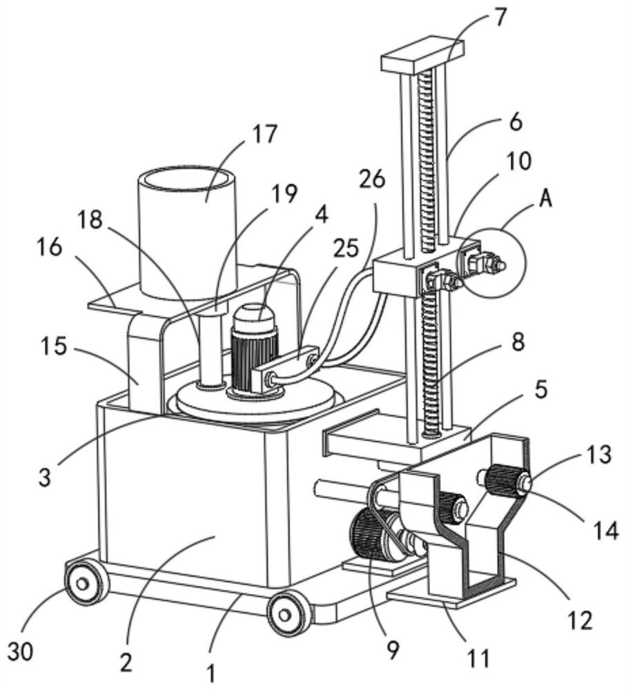
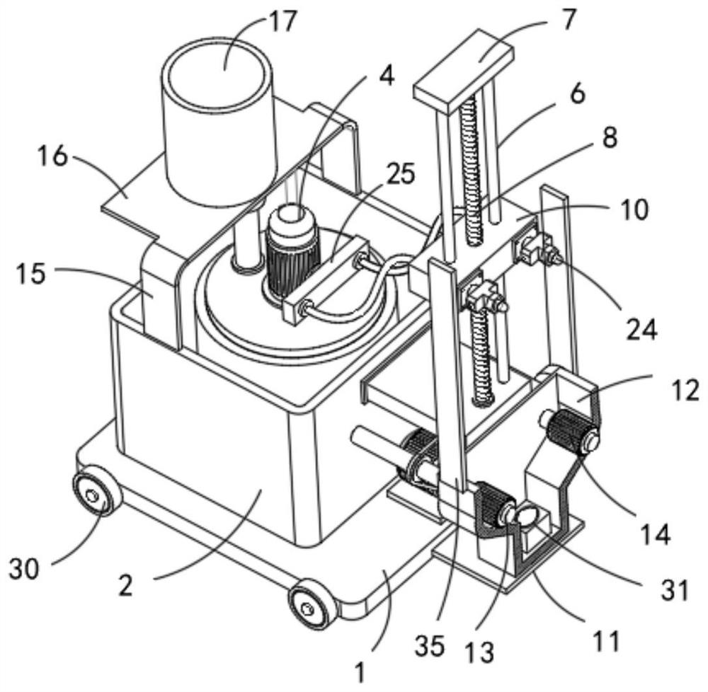
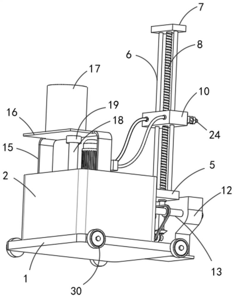
[0035] refer to Figure 1-7 , a wall paint spraying device, comprising a base plate 1 and a box body 2, two rollers 30 are rotatably connected to the front and rear side walls of the base plate 1, the box body 2 is fixedly connected to the upper end of the base plate 1, and the upper end of the box body 2 is Open structure, the inner bottom wall of the box body 2 is fixedly connected with the storage tank 3, the upper end of the storage tank 3 is fixedly connected with the pump body 4 connected with it, and the upper end of the box body 2 is provided with an automatic feeding device connected with the storage tank 3 mechanism, the automatic feeding mechanism includes a gantry support 15 fixedly connected to the upper end of the box body 2, a horizontal rectangular plate 16 is fixedly connected to the side wall of the gantry support 15, and a feeding barrel 17 is fixedly connected to the upper end of the rectangular plate 16. The lower end is fixedly connected with a feed pipe ...


PUM


Abstract

The invention belongs to the technical field of spraying machinery, and particularly relates to a wall coating spraying device which comprises a bottom plate and a box body; the front side wall and the rear side wall of the bottom plate are each rotationally connected with two rolling wheels; the box body is fixedly connected with the upper end of the bottom plate; the upper end of the box body is of an opening structure; a storage tank is fixedly connected with the inner bottom wall of the box body; the upper end of the storage tank is fixedly connected with a pump body communicated with the storage tank; the upper end of the box body is provided with an automatic feeding mechanism connected with the storage tank; the side wall of the box body is fixedly connected with a horizontal supporting plate; the upper end of the supporting plate is fixedly connected with two vertical sliding rods; the upper ends of the two sliding rods are fixedly connected with a same top plate; and the lower end of the top plate between the two sliding rods is rotationally connected with a vertical threaded rod. The wall coating spraying device has the advantages that coating dripping in the spraying process can be collected, so that the cleanliness of an environment during spraying is guaranteed; and automatic material supplementing can be conducted during long-term spraying operation, so that the labor intensity of workers is reduced, and the working efficiency is relatively improved.

Description

technical field [0001] The invention relates to the technical field of spraying machinery, in particular to a wall paint spraying device. Background technique [0002] Wall paint refers to the decoration and protection of the building wall, making the building wall beautiful and tidy, and at the same time protecting the building wall and prolonging its service life. According to the classification of building walls, wall coatings include two major parts: interior wall coatings and exterior wall coatings. [0003] For example, my country's patent application number CN201810820183.X, a wall paint spraying device with a disclosure date of 2018-12-07, its structure includes a paint storage device, a control handle, a suction motor, a suction pump, a nozzle, a suction nozzle, Adding pipe, the bottom end of the extraction motor is locked with a control handle and connected to the control handle, the right end of the extraction motor is locked with a suction pump, the bottom of the...

Claims


Application Information

Patent Timeline
Patent Type & Authority Applications(China)
IPC IPC(8): E04F21/12
CPCE04F21/12
Inventor 不公告发明人
Owner 魏君
Learn More