

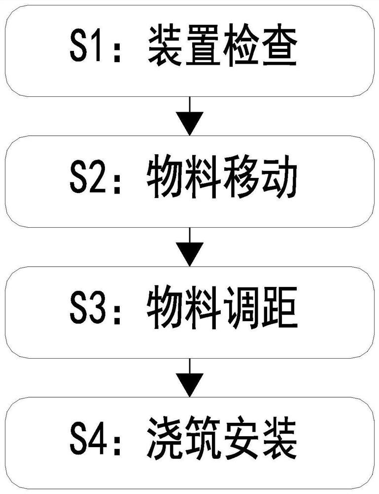
Prefabricated concrete part mounting and reinforcing method
A concrete prefabricated and prefabricated technology, applied in stairs, buildings, building structures, etc., can solve the problems of long time, economic loss, and many components required for the composition of the support bracket, so as to improve the hidden danger of safety and reduce the work intensity. Effect
- Summary
- Abstract
- Description
- Claims
- Application Information
AI Technical Summary
Problems solved by technology
Method used
Image

Examples
Embodiment Construction
[0036] The embodiments of the present invention are described in detail below with reference to the accompanying drawings, but the present invention can be implemented in many different ways as defined and covered by the claims.
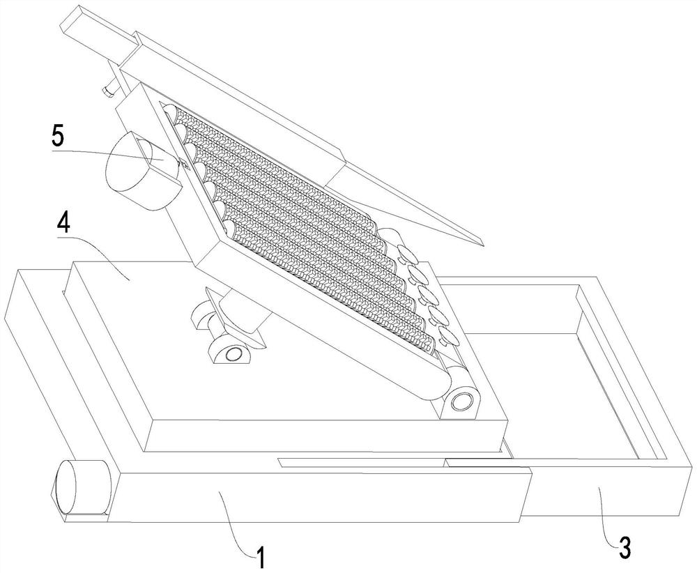
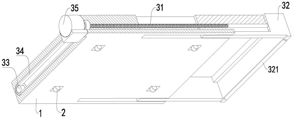
[0037] like Figure 1 to Figure 10 As shown, an installation and reinforcement method for prefabricated concrete prefabricated parts adopts the following installation and reinforcement device for prefabricated concrete prefabricated parts. , extension mechanism 3, adjustment mechanism 4 and transmission mechanism 5, the inner corner of the lower end of the base 1 is provided with a walking wheel 2, the right side of the base 1 is provided with an extension mechanism 3, the upper end surface of the base 1 is provided with an adjustment mechanism 4, and the upper end of the adjustment mechanism 4 is provided with There is a transmission mechanism 5;
[0038] During specific work, the present invention can support concrete prefabricated stairs with dif...
PUM
 Abstract
Description
Claims
Application Information