Miniature turbojet igniter

An igniter and turbojet technology, which is used in machines/engines, jet propulsion devices, turbines/propulsion fuel delivery systems, etc., can solve problems such as difficulty, prevent potential safety hazards, improve atomization effects, and reduce production costs. Effect

Pending Publication Date: 2021-07-16
ZHEJIANG YIDONG TECH CO LTD
View PDF0 Cites 0 Cited by
  • Summary
  • Abstract
  • Description
  • Claims
  • Application Information

AI Technical Summary

Problems solved by technology

[0004] Since the micro-turbine engine does not have a fuel atomization device, it is very difficult to directly ignite kerosene with an igniter

Method used


Image

  • Miniature turbojet igniter
  • Miniature turbojet igniter
  • Miniature turbojet igniter

Examples


Embodiment 1

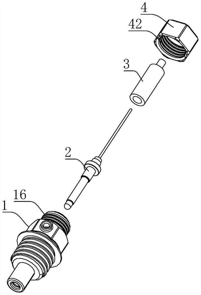
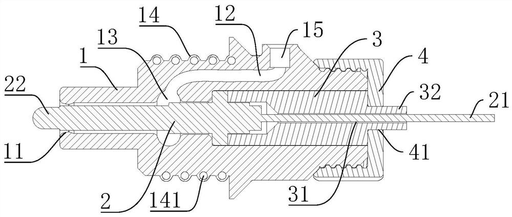
[0027] A miniature turbojet igniter, comprising an igniter housing 1, a heating core 2, an insulating ceramic body 3 and a cap 4; the igniter housing 1 is a hollow shell and wraps the insulating ceramic body 3, The insulating ceramic body 3 has a shaft hole 31 along the axial direction, the heating core 2 is inserted through the shaft hole 31 and exposes its positive end 21, and the cap 4 is connected to the igniter housing 1 The head, and the central hole 41 of the cap 4 surrounds the protruding part 32 of the insulating ceramic body 3; the negative end 22 of the heating core 2 passes through the shrinkage outlet at the tail of the igniter housing 1 11 and extend outward; the interior of the igniter housing 1 has an oil pipeline 12 and a pressure stabilizing chamber 13, and the oil passage communicates with the pressure stabilizing chamber 13.

Embodiment 2

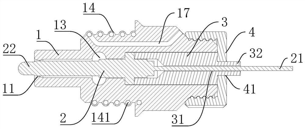
[0029] A miniature turbojet igniter, comprising an igniter housing 1, a heating core 2, an insulating ceramic body 3 and a cap 4; the igniter housing 1 is a hollow shell and wraps the insulating ceramic body 3, The insulating ceramic body 3 has a shaft hole 31 along the axial direction, the heating core 2 is inserted through the shaft hole 31 and exposes its positive end 21, and the cap 4 is connected to the igniter housing 1 The head, and the central hole 41 of the cap 4 surrounds the protruding part 32 of the insulating ceramic body 3; the negative end 22 of the heating core 2 passes through the shrinkage outlet at the tail of the igniter housing 1 11 and extend outward; the interior of the igniter housing 1 has an oil pipeline 12 and a pressure stabilizing chamber 13, and the oil passage communicates with the pressure stabilizing chamber 13.

[0030] The present invention can increase the initial velocity of the oil, improve the atomization effect, and increase the distance...


PUM


Abstract

The invention discloses a miniature turbojet igniter. The miniature turbojet igniter comprises an igniter shell, a heating core, an insulating ceramic body and a cap; the igniter shell is a hollow shell and wraps the insulating ceramic body, the insulating ceramic body is provided with a shaft hole in the axis direction, the heating core is inserted into the shaft hole in a penetrating mode, the positive electrode end of the heating core is exposed, the cap is connected to the head of the igniter shell, a center hole of the cap surrounds a protruding part of the insulating ceramic body, the negative electrode end of the heating core penetrates through a contraction type outlet in the tail part of the igniter shell and extends outwards. The miniature turbojet igniter is simple in structure, the igniter shell is integrally formed through the 3D printing technology, and an internal complex functional structure can be printed without adding a supporting structure; spherical hollow threads can generate proper deformation to adapt to the temperature, and a better sealing effect is obtained during thermal deformation; and the contraction type outlet can increase the initial speed of oil, improve the atomization effect and increase the flame distance.

Description

technical field [0001] The invention relates to the field of turbine engine control, in particular to a miniature turbojet igniter. Background technique [0002] Microturbine engine is an emerging research field based on modern advanced machining technology. It is a special aeroengine with the characteristics of small size, light weight and high thrust-to-weight ratio, and has broad application prospects in military and civilian fields. [0003] The microturbine engine has a unique design structure, which is different from the large aeroengine in control method and performance characteristics. First of all, the micro-turbine engine does not have a special electronic ignition device and fuel atomization device, but uses an evaporation tube to directly supply fuel into the combustion chamber. The traditional starting process is to pass propane gas into the combustion chamber for pre-combustion. After that, the fuel oil is heated and gasified when it flows through the evapora...

Claims


Application Information

Patent Timeline
Patent Type & Authority Applications(China)
IPC IPC(8): F02C7/264F02C7/22
CPCF02C7/264F02C7/222
Inventor 竺磊韩品连
Owner ZHEJIANG YIDONG TECH CO LTD
Why Eureka
Try Eureka