Fire-fighting pipe blockage detection mechanism
A detection mechanism and fire-fighting pipe technology, applied in the direction of pipe components, pipeline systems, mechanical equipment, etc., can solve problems such as difficulty, long distance of fire-fighting pipes, poor sealing effect, etc., and achieve the effect of improving adaptability
- Summary
- Abstract
- Description
- Claims
- Application Information
AI Technical Summary
Problems solved by technology
Method used
Image
Examples
Embodiment 1
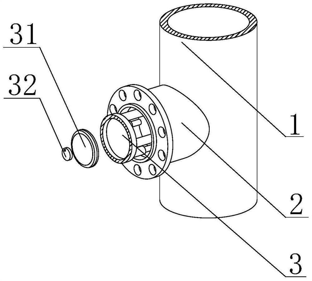
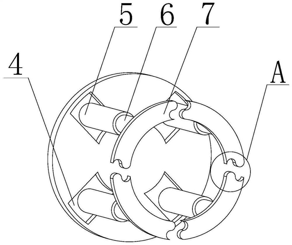
[0039] like Figure 1-8As shown, the present invention provides a fire-fighting pipe resistance detection mechanism, including a fire-fighting pipe 1 and a branch pipe 2, the outer wall of the branch pipe 2 is connected to the inner wall of the fire-fighting pipe 1, and the branch pipe 2 is arranged on the surface of the fire-fighting pipe 1 in sections, The inner wall of the branch pipe 2 is movably connected with a flow resistance detection device 3. Putting the flow resistance detection device 3 inside the adjacent branch pipe 2 can form a closed space in this section, so as to facilitate the segmental detection of the fire pipe 1 for blockages. , to improve the accuracy of the detection of the resistance of the fire pipeline 1, the inner wall of the resistance detection device 3 is fixedly installed with a water body pressure sensor 31 and a data transmission module 32, and the water body pressure sensor 31 provided can monitor the closed space in the fire protection pipeli...
Embodiment 2
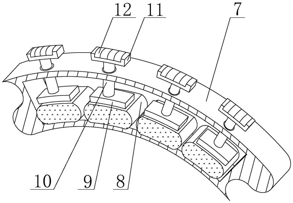
[0044] like Figure 1-8 As shown, on the basis of Embodiment 1, the present invention provides a technical solution: preferably, an elastic pressure receiving device 8 is fixedly installed on the bottom of the inner wall of the blocking block 7, and a contact block 9 is overlapped above the elastic pressure receiving device 8 , the elastic pressure device 8 has elastic potential energy. When the contact block 9 moves, it will squeeze the elastic pressure device 8. The top of the contact block 9 is fixedly connected with a moving column 10, and the outer wall of the moving column 10 runs through the blocking block. 7, and the moving column 10 is elastically connected to the blocking block 7 through the elastic pressure device 8 arranged on the contact block 9, and the top of the moving column 10 is fixedly connected with a condensation joint plate 11, which is located at the end of the blocking block 7 It is installed on the side, and the top of the inner wall of the shrinkage ...
Embodiment 3
[0048] like Figure 1-8 As shown, on the basis of Embodiment 1, the present invention provides a technical solution: preferably, the elastic compression device 8 includes a high elastic connection belt 16 and a hard plate 17, and the right side of the high elasticity connection belt 16 is connected to the The left side of the back-shaped hard plate 17 is fixedly connected, and the top of the highly elastic connecting band 16 is overlapped with the bottom of the contact block 9. When the contact block 9 moves down, the high elastic connecting band 16 will be squeezed, so that the elastic The space inside the pressure device 8 is reduced, causing the air pressure to increase. The inner side of the hard plate 17 is fixedly equipped with a counterweight plate 18, and the counterweight plate 18 is provided to act as a counterweight to the elastic pressure device 8. function, to prevent the contact block 9 from being displaced when in contact with the highly elastic connecting belt ...
PUM
 Abstract
Description
Claims
Application Information
 - R&D
- Intellectual Property
- Life Sciences
- Materials
- Tech Scout
- Unparalleled Data Quality
- Higher Quality Content
- 60% Fewer Hallucinations
Browse by: Latest US Patents, China's latest patents, Technical Efficacy Thesaurus, Application Domain, Technology Topic, Popular Technical Reports.
© 2025 PatSnap. All rights reserved.Legal|Privacy policy|Modern Slavery Act Transparency Statement|Sitemap|About US| Contact US: help@patsnap.com


