

Bearing testing machine based on three-direction vibration
A technology of bearing test and lateral vibration, which is applied in the direction of vibration test, mechanical component test, machine/structural component test, etc. It can solve the problem that the real vibration of the bearing cannot be simulated, and achieve the effect of accurate test results
- Summary
- Abstract
- Description
- Claims
- Application Information
AI Technical Summary
Problems solved by technology
Method used
Image

Examples
Embodiment 1
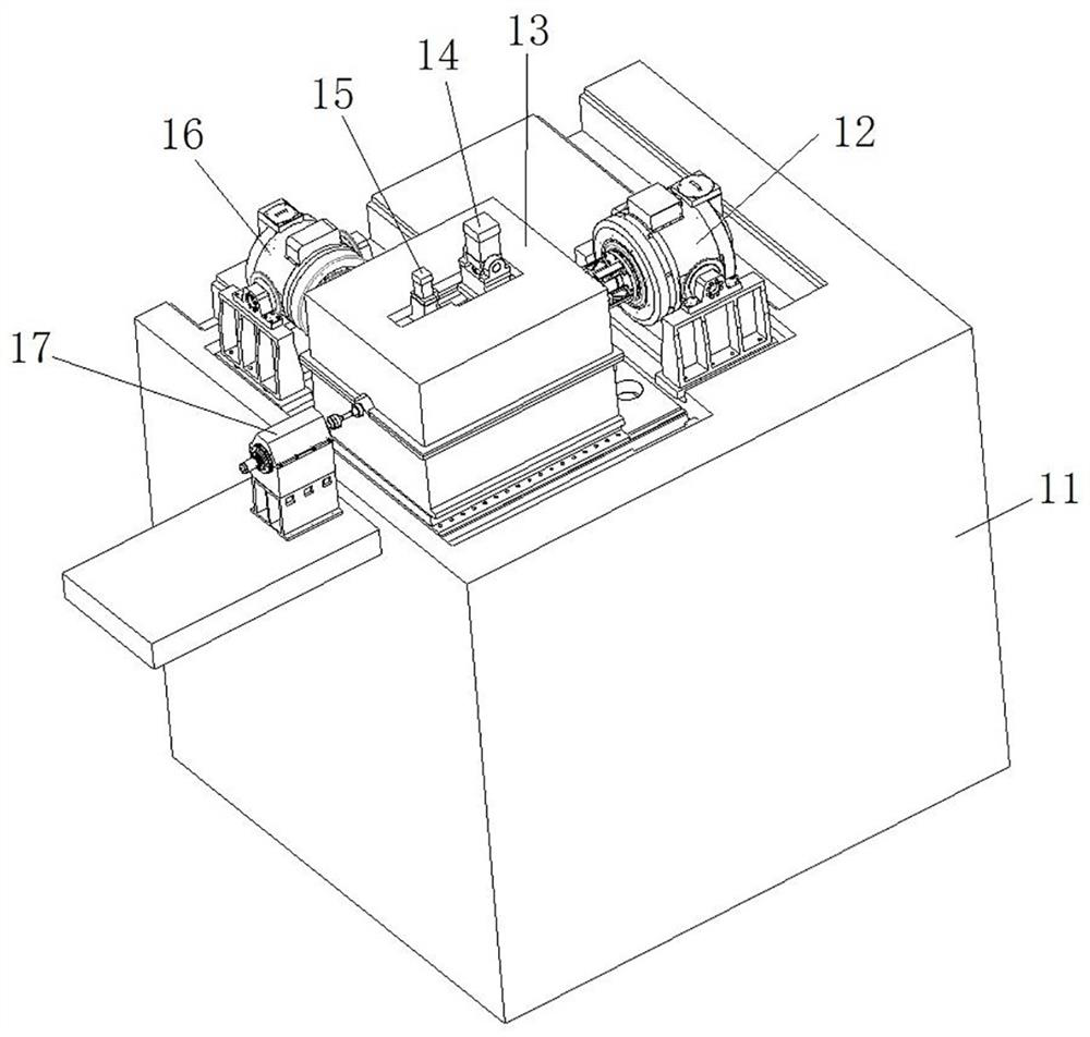
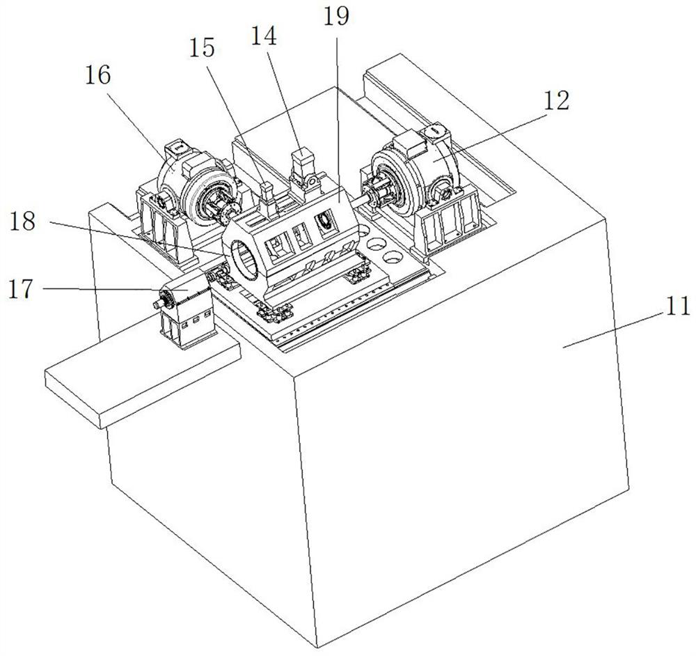
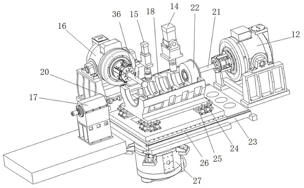
[0047] Such as Figure 1 to Figure 6As shown, the bearing testing machine based on three-way vibration includes a cement box 11. A test bench is installed on the cement box 11. A test body is floatingly mounted above the test bench. The test body includes a main body base 18 and a main body cover plate 19. The main body base 18 It has a bearing supporting part for supporting the bearing fitted on the test shaft 37 .
[0048] In this embodiment, the test stand includes a base 23 and an adjustment stand 26 , and the adjustment stand 26 is slidably assembled on the base 23 along the axial direction of the test axis 37 . Specifically, such as Figure 3 to Figure 5 As shown, the upper side of the base 23 is provided with a T-shaped groove extending axially along the test axis 37, and the adjustment platform 26 is connected with bolts, and there are a plurality of bolts arranged at intervals along the axial direction of the test axis 37, and the bolt heads of each bolt All are in ...
Embodiment 2
[0065] The difference between this embodiment and Embodiment 1 is that in Embodiment 1, the damping element is a rubber block 24; in this embodiment, the damping element is a compression spring.
Embodiment 3
[0067] The difference between this embodiment and Embodiment 1 is that in Embodiment 1, a guide rod is provided between the test body and the test bench, and the rubber block 24 is set on the guide rod to ensure the stability of the rubber block. In this embodiment, a limit sleeve is fixed on the test bench, and the rubber block is placed in the limit sleeve to ensure the stability of the rubber block. The rubber block is higher than the limit sleeve to prevent the test body from compressing the rubber. When the block hits the limit sleeve, it will affect the test results.
PUM
 Abstract
Description
Claims
Application Information