Scanning device for product surface detection and assembling method thereof

A surface detection and scanning device technology, which is applied in the direction of measuring devices, instruments, scientific instruments, etc., can solve the problems of occupying the detection environment, large size of the device, unstable use, etc., and achieve the goal of reducing the volume, stabilizing the space state, and avoiding stray light Effect

Active Publication Date: 2021-07-16
江苏善果缘智能科技有限公司
View PDF9 Cites 0 Cited by
  • Summary
  • Abstract
  • Description
  • Claims
  • Application Information

AI Technical Summary

Problems solved by technology

[0003] At present, when detecting defects on the surface of an object, a scanning device with a CCD camera is usually used, and the light source is used to irradiate the surface of the object to make the light path reflect from the surface of the object, and then the CCD collects the reflected light path. However, the currently used scanning device is for Ensuring that the amount of light collected is sufficient and the path of the light is long enough will lead to a large volume of the entire device, which will seriously occupy the space of the detection environment, and it is also unstable and easy to shake during use

Method used


Image

  • Scanning device for product surface detection and assembling method thereof
  • Scanning device for product surface detection and assembling method thereof
  • Scanning device for product surface detection and assembling method thereof

Examples


Embodiment Construction

[0055] In order to make the technical solutions of the present invention clearer and clearer to those skilled in the art, the present invention will be further described in detail below in conjunction with the examples and accompanying drawings, but the embodiments of the present invention are not limited thereto.

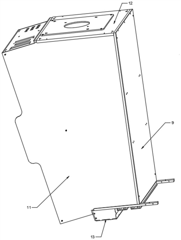
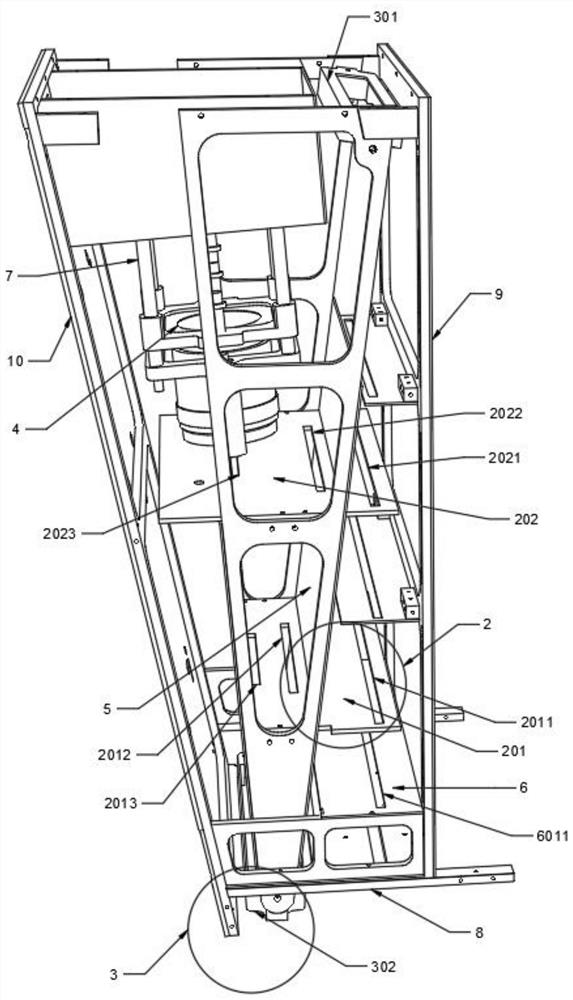
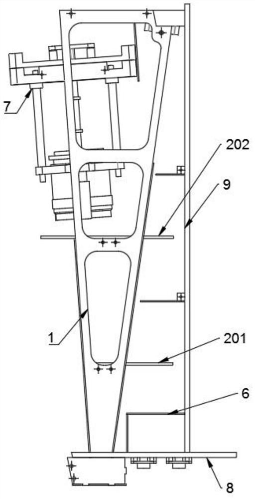
[0056] Such as Figure 1-Figure 4 As shown, the scanning device for product surface detection provided by this embodiment includes a mounting bracket 1, and an aperture part 2 is fixed on one side of the mounting bracket 1. The reflected light generated on the surface of the inspected product passes through to form a folded optical path. The external light refers to the light reflected by the surface of the object to be inspected. One side of the mounting bracket 1 is also provided with an optical reflection component 3 for multiple reflections from the light. The optical path passing through the channel of the diaphragm part 2 makes the optical path form an end-to...


PUM


Abstract

The invention discloses a scanning device for product surface detection and an assembling method thereof, and relates to the technical field of product surface scanning devices. The scanning device comprises a mounting support, a diaphragm component is fixed to one side of the mounting support, and a plurality of channels penetrate through the surface of the diaphragm component and are used for allowing reflected light generated by the surface of a to-be-detected product to pass through so as to form a folded light path; and a light path reflecting component is further arranged on one side of the mounting support. Light can pass through the diaphragm component to form a light path, stray light is effectively avoided, the diaphragm component is used in cooperation with the light path reflection component, an original light path is divided into a plurality of light paths, the purpose of reducing the size of the whole device is achieved, meanwhile, the internal structure of the scanning device is compact, the scanning device has high stability in use. The mounting bracket fixedly connected with the diaphragm component and the reflecting component respectively is not in contact with the cover plate and the side plate, so that the cover plate and the side plate can be prevented from colliding with the diaphragm component and the reflecting component.

Description

technical field [0001] The invention relates to the technical field of product surface scanning devices, in particular to a scanning device for product surface detection and an assembly method thereof. Background technique [0002] CCD sensor, made of a high-sensitivity semiconductor material, can convert light into electric charge, and convert it into digital signal through analog-to-digital converter for computer to process it. At present, it has been widely used in the detection of surface defects of industrial products. Especially for the detection of various defects on the product surface. [0003] At present, when detecting defects on the surface of an object, a scanning device with a CCD camera is usually used, and the light source is used to irradiate the surface of the object to make the light path reflect from the surface of the object, and then the CCD collects the reflected light path. However, the currently used scanning device is for Ensuring that the amount ...

Claims


Application Information

Patent Timeline
Patent Type & Authority Applications(China)
IPC IPC(8): G01N21/892G01N21/01
CPCG01N21/892G01N21/01G01N2021/0112
Inventor 周维郑步笑徐存辉陈立新
Owner 江苏善果缘智能科技有限公司
Why Eureka
Try Eureka