Supercharge Your Innovation With Domain-Expert AI Agents!

Noise source positioning method based on multiple microphone arrays

A technology of a microphone array and a positioning method, which is applied in the field of sound source positioning, can solve problems such as low positioning accuracy and affect application reliability, and achieve the effect of eliminating background noise.

Active Publication Date: 2021-07-16
上海盈蓓德智能科技有限公司 +1
View PDF14 Cites 5 Cited by
  • Summary
  • Abstract
  • Description
  • Claims
  • Application Information

AI Technical Summary

Problems solved by technology

In the cabin, due to environmental constraints, the distance from the sound source to the microphone array is relatively short, and the relationship between the sound amplitude and the di

Method used


Image

  • Noise source positioning method based on multiple microphone arrays
  • Noise source positioning method based on multiple microphone arrays
  • Noise source positioning method based on multiple microphone arrays

Examples


Embodiment 1

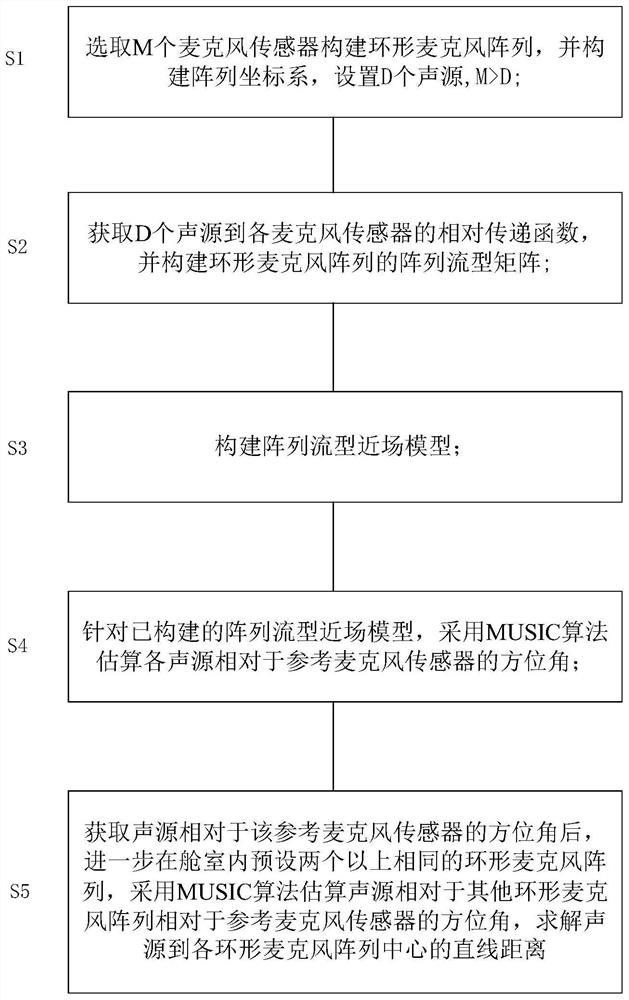
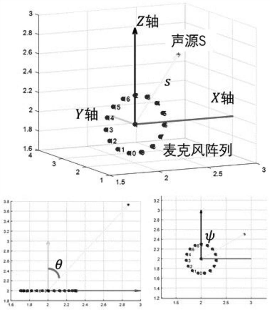
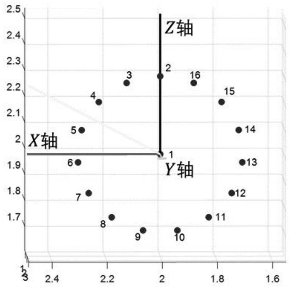
[0061] Embodiment 1: There are three independent single-frequency sound sources in the cabin, and the sound pressure signals of the noise sources are: P S1 =R 1 (t)sin(2πf 1 t); P S2 =R 2 (t)sin(2πf 2 t); P S3 =R 3 (t)sin(2πf 3 t); R 1 (t), R 2 (t) and R 3 (t) is the fluctuation coefficient of the amplitude of the sound source, which is a random real number in the interval (0.7, 1) here; the frequencies of each sound source are: f 1 = 300Hz, f 2 = 500Hz, f 3 =700Hz, the three sound sources produce three different sound waves, assuming the sampling time is 2 seconds, the coordinates of the three sound sources in the fixed coordinate system are:

[0062] (0.8660, 1.7321, 0.5000)m; (0, 1.5, 0)m; (-0.9766, 0.4104, -0.5638)m;

[0063] The distances from the three sound sources to the center of the ring microphone array are [2, 1.5, 1.2] m respectively, and the azimuth angle [θ 1 , θ 2 , θ 3 ] = [30, 0, 70] degrees, [ψ 1 , ψ 2 , ψ 3 ]=[60, intention value, 240] de...

Embodiment 2

[0068] Embodiment 2: There are three independent dual-frequency sound sources in the cabin, and the sound pressure signals of the noise sources are respectively: R 11 (t)sin(2πf 11 t)+R 12 (t)sin(2πf 12 t); R 21 (t)sin(2πf 21 t)+R 22 (t)sin(2πf 22 t); R 31 (t)sin(2πf 31 t)+R 32 (t)sin(2πf 32 t); R 11 (t), R 12 (t), R 21 (t), R 22 (t), R 31 (t) and R 32 (t) are the fluctuation coefficients of the amplitude of the sound source, where the value is a random real number in the interval (0.7, 1); the frequencies of each sound source are respectively: f 11 = 300Hz, f 12 = 600Hz, f 21 = 500Hz, f 22 = 1000Hz, f 31 =700Hz, f 32 =1400Hz; the three sound sources generate six different sound waves, the sampling time is set as 2 seconds, and the coordinates of the three sound sources in the fixed coordinate system are the same as those in the embodiment.

[0069] Similarly, the acoustic finite element module of Comsol commercial software was used to verify the physical ...


PUM


Abstract

The invention provides a noise source positioning method based on a plurality of microphone arrays, which comprises the following steps of: selecting M microphone sensors to construct an annular microphone array, setting a microphone sensor as a reference microphone sensor, and establishing an array coordinate system by using the reference microphone sensor, wherein the rest M-1 microphone sensors are arranged around the reference microphone sensor, and D sound sources are arranged in the cabin; obtaining a relative transfer function from the D sound sources to each microphone sensor, and constructing an array flow pattern matrix of the annular microphone array; further introducing the linear distance between the sound source and the reference microphone sensor, the azimuth angle of the sound source relative to the reference microphone sensor and the sound source frequency to construct an array flow pattern near-field model; estimating the azimuth angle of each sound source relative to the reference microphone sensor by adopting a MUSIC algorithm; and presetting more than two same annular microphone arrays in a cabin, estimating the azimuth angles of the sound sources relative to each annular microphone array relative to the reference microphone sensor, and generally solving the distance from the sound sources to each annular microphone array by using a least square method.

Description

technical field [0001] The invention relates to the field of sound source localization, in particular to a noise source localization method based on multiple microphone arrays. Background technique [0002] Sound source localization plays a very important role in the processing of sound signals. It is widely used in aspects such as smart devices, video conferencing systems, violation capture or fault diagnosis, and can automatically capture and align sound objects. It obtains the direction of arrival from the sound source to the entire array of microphones by processing the collected signals. Compared with a single microphone sensor, the microphone array composed of multiple microphone sensors has better advantages in speech signal processing, and the microphone array is complementary. Can better eliminate background noise. In the cabin, due to environmental constraints, the distance from the sound source to the microphone array is relatively short, and the relationship bet...

Claims


Application Information

Patent Timeline
IPC IPC(8): G01S5/22
CPCG01S5/22Y02T90/00
Inventor 杨恺管龙腾何将赢苏克玮
Owner 上海盈蓓德智能科技有限公司
Features
  • R&D
  • Intellectual Property
  • Life Sciences
  • Materials
  • Tech Scout
  • Unparalleled Data Quality
  • Higher Quality Content
  • 60% Fewer Hallucinations
Learn More