
Bidirectional speed stabilizing controller for DC motor

A technology of DC motors and controllers, which is applied in the direction of excitation or armature current control, etc. It can solve the problems of accuracy requirements and work stability that affect the steady speed, unfavorable applicability requirements, poor anti-interference ability, etc., and achieve convenient design modification , Improve system integration and strong adaptability

Inactive Publication Date: 2012-09-19
CHANGCHUN INST OF OPTICS FINE MECHANICS & PHYSICS CHINESE ACAD OF SCI
View PDF0 Cites 0 Cited by
  • Summary
  • Abstract
  • Description
  • Claims
  • Application Information

AI Technical Summary

Problems solved by technology

[0003] At present, for the controllers that use the permanent magnet DC torque-tachometer unit to drive the load at a constant speed and steady rotation in two directions, most of the controllers are complex in design, high in cost, cumbersome in debugging, and are easily affected by electromagnetic interference from the power level of the motor drive. Poor, which in turn affects the precision requirements and work stability of the steady speed, which is not conducive to the wide application requirements. In view of the situation that the permanent magnet DC torque-tachometer unit is used to drive the load at a constant speed, steady speed, and two-way rotation, the invention designs a A Bidirectional Speed ​​Steady Speed ​​Controller for DC Motor

Method used


Image

  • Bidirectional speed stabilizing controller for DC motor
  • Bidirectional speed stabilizing controller for DC motor
  • Bidirectional speed stabilizing controller for DC motor

Examples


Embodiment Construction

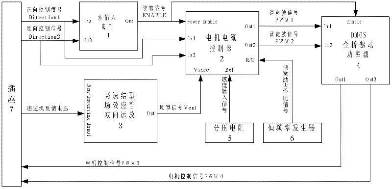
[0016] The following is attached figure 1 , Attached figure 2 The given implementation examples further describe the present invention in detail. Reference figure 1 As shown, it includes dual-input OR gate 1, motor current controller 2, high-speed junction field effect transistor bidirectional operational amplifier 3, DMOS full bridge drive power stage 4, voltage divider resistor 5, constant frequency waveform generator 6, socket 7; Socket 7 receives the external control direction signal Direction1 forward control signal and Direction2 reverse control signal, and connects them to the signal input pins InA and InB of dual-input OR gate 1. Dual-input OR gate 1 uses TI’s SN54LS32, Used to integrate the socket 7 receiving the external control direction signal Direction1 forward control signal and Direction2 reverse control signal to generate the ENABLE enable signal; after dual input OR gate 1 or comparison, the signal output pin Out pin outputs the ENABLE enable signal and Con...


PUM


Abstract

The invention relates to a bidirectional speed stabilizing controller for a DC motor, and belongs to the technical field of electronic application. The bidirectional speed stabilizing controller comprises a double input OR gate, a motor current controller, a high-speed junction-type field-effect transistor bidirectional operational amplifier, a DMOS full-bridge driving power stage, a divider resistor, a constant frequency waveform generator, and a socket, wherein the motor current controller combines signals such as a forward control signal, a reversed control signal, an enable signal, a speed input signal, a feedback signal and a pulse width modified wave duty ratio signal into a speed closed loop circuit; and after integration, pulse width modified wave signals PWM1 and PWM2 are output,are subjected to driving amplification of the DMOS full-bridge driving power stage and enabled by the enable signal; and finally, the DMOS full-bridge driving power stage outputs motor control signals PWM3 and PWM4 to control the magnitude and direction of the rotation of the motor. The bidirectional speed stabilizing controller ensures that the motor drives the load to rotate bidirectionally at a constant and stable speed, and has the characteristics of simple structure, convenient regulation, high precision, strong practicability and the like.

Description

Technical field [0001] The invention belongs to the technical field of electronic applications, and particularly relates to the design of a bidirectional speed steady-speed controller for a DC motor. technical background [0002] In recent years, with the development of power electronics technology and the progress of its application technology, as well as the continuous appearance of various special integrated components, the DC servo motor control technology has made significant progress, and its application range has become wider and wider, especially PWM servo control. Technology has received universal attention. [0003] At present, most of the controllers that use permanent magnet DC torque-speed measuring unit to drive the load at a constant speed and rotate at a steady speed are mostly complicated in design, high in cost, cumbersome to debug, and are susceptible to electromagnetic interference from the motor drive power level, and anti-interference ability This in turn aff...

Claims


Application Information

Patent Timeline
Patent Type & Authority Patents(China)
IPC IPC(8): H02P7/29
Inventor 杜璧秀张淑梅王志乾李建荣
Owner CHANGCHUN INST OF OPTICS FINE MECHANICS & PHYSICS CHINESE ACAD OF SCI
Learn More