Limited soil body soil pressure acquisition method considering soil separation width in adjacent underground project

An earth pressure and soil separation technology, which can be used in basic structural engineering, excavation, construction, etc., to solve problems such as insecurity, soil deformation and extrusion limitations in foundation pits, and reducing the ability of soil to passively resist the effect of support prestress. , to achieve the effect of high reliability, simple calculation method and reliable theory

Active Publication Date: 2021-07-16
RES INST OF HIGHWAY MINIST OF TRANSPORT +2
View PDF5 Cites 1 Cited by
  • Summary
  • Abstract
  • Description
  • Claims
  • Application Information

AI Technical Summary

Problems solved by technology

When affected by the surrounding dense buildings and the environment, the deformation and extrusion of the foundation pit soil are limited, and it is not safe to use the standard algorithm to calculate the active and passive earth pressure of the soil
When dealing with soil pressure and stability in the traditional method, the theory of Rankine earth pressure or Coulomb earth pressure is adopted, and the assumed slip surface extends from the bottom of the foundation pit to the surface in a straight line. Therefore, for the situation where the surrounding surface range is insufficient, This assumption is unsatisfactory
Especially for the simultaneous excavation of foundation pits on both sides with intervening soil in the adjacent underground project, the width of the interlayer of the adjacent project limits the effective range of the active earth pressure of the soil and reduces the passive resistance of the soil to the prestress of the internal support. ability to act

Method used


Image

  • Limited soil body soil pressure acquisition method considering soil separation width in adjacent underground project
  • Limited soil body soil pressure acquisition method considering soil separation width in adjacent underground project
  • Limited soil body soil pressure acquisition method considering soil separation width in adjacent underground project

Examples


Embodiment 1

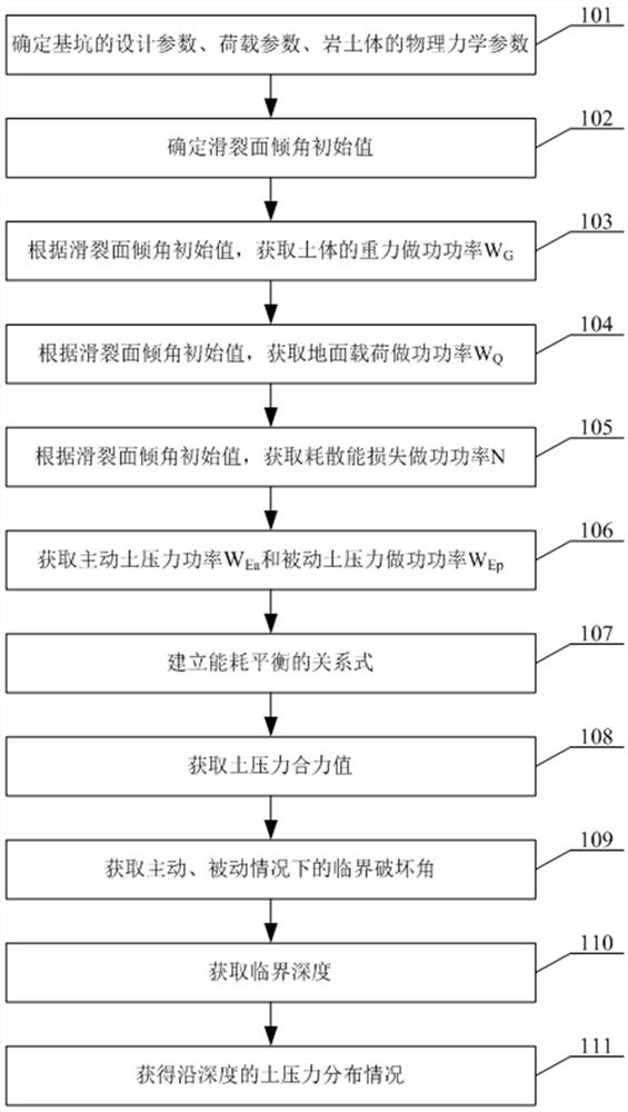
[0096] figure 1 For the flow chart of the method for obtaining the earth pressure of the limited soil body considering the width of the earth in the adjacent underground engineering according to the present invention, the following will refer to figure 1 , a detailed description of the method for obtaining the limited soil earth pressure of the present invention that considers the width of the separation soil in the adjacent underground engineering.

[0097] First, in step 101, the design parameters of the foundation pit, the surface load parameters, and the physical and mechanical parameters of the rock and soil mass are determined.

[0098] In the embodiment of the present invention, the design parameters of the foundation pit are determined by the design scheme, including the width S of the intermediate soil and the depth H of the foundation pit under the current excavation process.

[0099] In the embodiment of the present invention, the surface load parameter is the over...

Embodiment 2

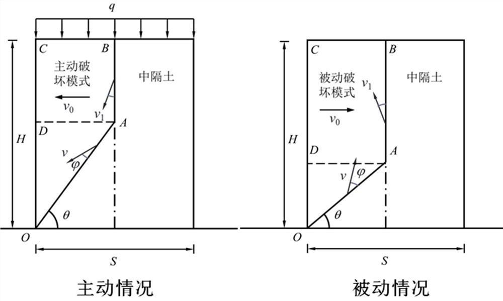
[0178] figure 2 It is a schematic diagram of the earth pressure calculation model of the finite soil body with intermediate soil according to the present invention, such as figure 2 As shown in the figure, under the condition of the existence of intermediate soil with limited width, the excavation construction on both sides of the foundation pit is performed simultaneously, and the earth pressure under active and passive conditions is only provided by the intermediate soil of half the width. During active failure, the soil is displaced toward the inside of the foundation pit, and the virtual velocity on the fracture surface is at a certain angle to the fracture surface and points to the side of the foundation pit. During passive failure, the soil body is displaced away from the foundation pit, and the virtual velocity on the fracture surface is at a certain angle to the fracture surface and faces away from the foundation pit.

[0179] In the embodiment of the present invent...

Embodiment 3

[0182] Embodiments of the present invention also provide an electronic device, Figure 4 It is a schematic structural diagram of an electronic device according to the present invention, such as Figure 4 As shown, the electronic device 40 of the present invention includes a processor 401 and a memory 402, wherein,

[0183] The memory 402 stores a computer program, and when the computer program is read and executed by the processor 401 , the computer program executes the steps in the above-mentioned embodiment of the method for obtaining the limited soil mass and earth pressure considering the width of the partition in the adjacent subterranean project.


PUM


Abstract

The invention discloses a limited soil mass soil pressure acquisition method considering the soil separation width in an adjacent underground project. The method comprises the following steps of determining foundation pit design parameters, load parameters and physical and mechanical parameters of a rock-soil mass; determining an initial slip crack surface inclination angle; acquiring the gravity acting power, the ground load acting power, the dissipated energy loss acting power and the pressure acting power of the soil body; establishing a relational expression of energy consumption balance, and obtaining a soil pressure resultant force value and a critical failure angle; and obtaining a critical depth, and obtaining a soil pressure distribution condition along the depth. According to the limited soil mass soil pressure acquisition method considering the soil separation width in the adjacent underground project, the excavation safety of foundation pits on the two sides of the soil separation in the adjacent underground project can be evaluated and predicted in advance, and a basis is provided for design of an inner support.

Description

technical field [0001] The invention relates to the technical field of geotechnical engineering, in particular to a method for obtaining earth pressure of a limited soil body. Background technique [0002] Generally, the excavation of foundation pits has higher requirements on site conditions, and there are no other buildings near the foundation pits. When affected by the surrounding dense buildings and the environment, the deformation and extrusion of the foundation pit soil are limited, and it is not safe to use the standard algorithm to calculate the active and passive earth pressure of the soil. When dealing with soil pressure and stability in the traditional method, the theory of Rankine earth pressure or Coulomb earth pressure is adopted, and the assumed slip surface extends from the bottom of the foundation pit to the surface in a straight line. Therefore, for the situation where the surrounding surface range is insufficient, This assumption cannot be satisfied. Esp...

Claims


Application Information

Patent Timeline
Patent Type & Authority Applications(China)
IPC IPC(8): G06F30/23E02D17/02E02D17/04G06F119/02G06F119/14
CPCE02D17/02E02D17/04G06F30/23G06F2119/02G06F2119/14
Inventor 张翾王华牢曲宏福付金冯春蕾李雪峰吴圣智
Owner RES INST OF HIGHWAY MINIST OF TRANSPORT
Why Eureka
Try Eureka