Rotatable pin insulator

A pin-type insulator, insulator technology, applied in the direction of pin-type insulators, insulators, electrical components, etc., can solve the problems of no cable retraction and fastening, insulator clips can not be disassembled and installed, etc., to improve efficiency, The effect of improving usability and usability

Active Publication Date: 2021-07-16
江西省萍乡市富源瓷业有限公司
View PDF5 Cites 0 Cited by
  • Summary
  • Abstract
  • Description
  • Claims
  • Application Information

AI Technical Summary

Problems solved by technology

[0004] In view of the above situation, in order to overcome the defects of the prior art, the present invention provides a rotatable pin insulator, which effectively solves the problem that the existing pin insulators in the above background technology do not have the function of retracting and fastening the cables. At the same time, the clamp head on the top of the insulator cannot be disassembled and installed

Method used


Image

  • Rotatable pin insulator
  • Rotatable pin insulator
  • Rotatable pin insulator

Examples


Embodiment 1

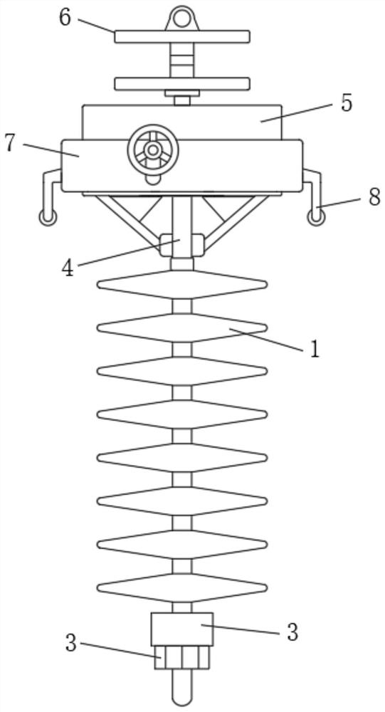
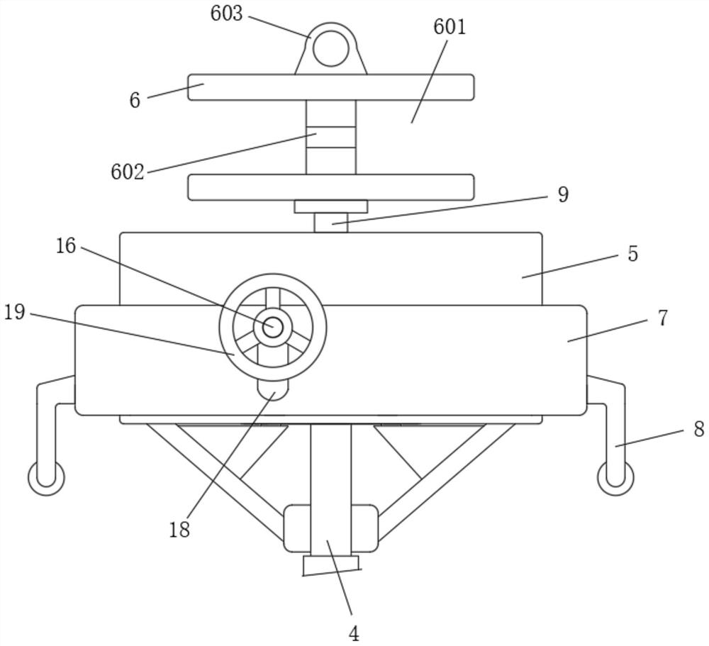
[0028] Embodiment one, by Figure 1 to Figure 4 Given, the present invention includes a pin insulator body 1, a connecting threaded pin 2 is installed on the bottom of the pin insulator body 1, a fixing nut 3 is connected to the surface of the connecting threaded pin 2, and a connecting rod 4 is installed on the top of the pin insulator body 1 , a fixed block 5 is installed on the top of the connecting rod 4, a cable reel 6 is installed on the top of the fixed block 5, a cover box 7 is installed on the surface of the fixed block 5, and an operating lever is fixedly installed on the bottom of both ends of the cover box 7 8;

[0029] The top of the connecting rod 4 is fixedly connected with a block 401, and the middle part of the bottom of the fixed block 5 is provided with a groove 501, and the block 401 is snapped in the inside of the groove 501. By setting the block 401 and the groove 501, the fixed block 5. Can be installed stably and effectively;

[0030] The middle part ...

Embodiment 2

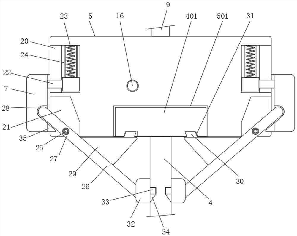
[0031] Embodiment two, on the basis of embodiment one, by Figure 4 Given, the surface of the rotating gear 11 is meshed with a fixed locking tooth 12, one end of the fixed locking tooth 12 is rotated and installed inside the adjustment cavity 10 through a fixed pin 13, and an extrusion plate 14 is fixedly installed on the upper part of the fixed locking tooth 12. A return spring 15 is installed between one side of the pressure plate 14 and the side wall of the adjustment cavity 10 , so that the fixed latch 12 can stably and effectively fix the rotating gear 11 .

Embodiment 3

[0032] Embodiment three, on the basis of embodiment two, by figure 2 , image 3 with Figure 4Given, the other side of the extrusion plate 14 is provided with a runner 17, and the circumferential surface of the runner 17 is equidistantly provided with extrusion bumps, and the ends of the extrusion bumps are in rolling contact with the other side of the extrusion plate 14. , the middle part of the runner 17 is rotatably equipped with a turn bar 16, and the turn bar 16 is rotatably installed in the inside of the adjustment chamber 10, so that the fixed latch 12 can be regulated so as to be separated from the turn gear 11.


PUM


Abstract

The invention belongs to the technical field of pin type insulators, and discloses a rotatable pin type insulator, and aims to solve the problem that an existing pin type insulator does not have the functions of winding, unwinding and fastening a cable and the problem that a wire clamping head at the top of the insulator cannot be disassembled and assembled at the same time. The rotatable pin type insulator comprises a pin type insulator body, the bottom of the pin type insulator body is provided with a connecting threaded pin, the surface of the connecting threaded pin is connected with a fixing nut, the top of the pin type insulator body is provided with a connecting rod, the top of the connecting rod is provided with a fixing block, and the top of the fixing block is provided with a cable winding disc. According to the pin type insulator, rotation adjustment can be effectively carried out, so that a cable can be effectively wound, unwound and fastened, the cable installation efficiency is improved, meanwhile, a cable clamping head of the pin type insulator can be effectively installed and detached, the use performance and practicability of the pin type insulator are improved, and the use and maintenance of the pin type insulator are facilitated.

Description

technical field [0001] The invention belongs to the technical field of pin insulators, in particular to a rotatable pin insulator. Background technique [0002] Pin-type insulators are components used to support or suspend wires and form electrical insulation between towers and wires; pin-type ordinary ceramic insulators and cast steel are glued together with cement adhesive, and the surface of the porcelain parts Coated with a layer of glaze to improve the insulating properties of the insulator. [0003] The existing pin-type insulator has the function of retracting and fastening the cable during installation and use, which leads to low installation efficiency of the cable. At the same time, the clamping head on the top of the insulator cannot be disassembled and installed, resulting in damage to the clamping head. Finally, the insulator needs to be replaced as a whole; therefore, it needs to be improved in view of the current situation. Contents of the invention [000...

Claims


Application Information

Patent Timeline
Patent Type & Authority Applications(China)
IPC IPC(8): H01B17/22H01B17/38
CPCH01B17/22H01B17/38
Inventor 聂珂
Owner 江西省萍乡市富源瓷业有限公司
Why Eureka
Try Eureka