Clamping device of three-dimensional wound core transformer and transformer

A technology of three-dimensional wound iron core and clamping device, which can be used in transformer/inductor parts, transformer/inductor coil/winding/connection, prevention/reduction of unnecessary electric/magnetic influence, etc., and can solve no-load loss , heavy weight, increased noise, etc., to achieve the effect of reducing steel consumables, simple structure, and light weight

Pending Publication Date: 2021-07-16
HAIHONG ELECTRIC CO LTD
View PDF0 Cites 2 Cited by
  • Summary
  • Abstract
  • Description
  • Claims
  • Application Information

AI Technical Summary

Problems solved by technology

[0003] In the related art, three-dimensional wound core transformers are usually equipped with clamping devices, which are used to provide support for the coil windings during the assembly and operation of the transformer, so as to avoid the displacement of the coil windings and affect the performance of the transformer, resulting in no-load loss and noise increase
[0004] The traditional clamping device mainly includes an upper clamp and a lower clamp, which are generally equilateral triangle frames. The upper clamp and the lower clamp are welded by steel plates or section steel. As a whole, the upper clamp and the lower clamp are connected by multiple screw components, which occupy a large volume overall, are heavy in weight, and require more consumables for manufacturing

Method used


Image

  • Clamping device of three-dimensional wound core transformer and transformer
  • Clamping device of three-dimensional wound core transformer and transformer

Examples


Embodiment Construction

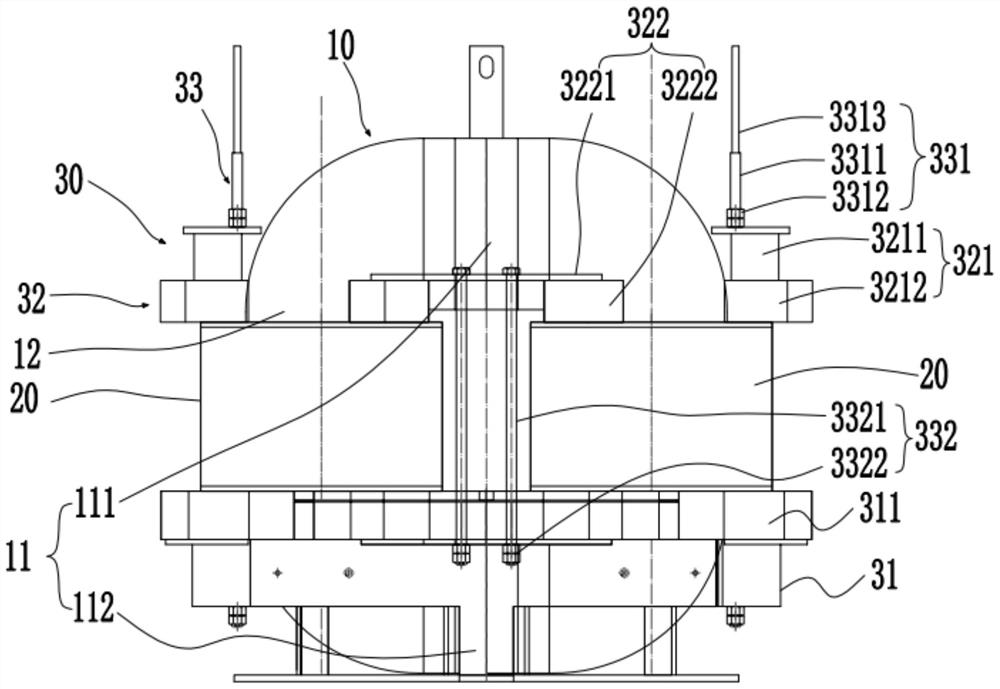
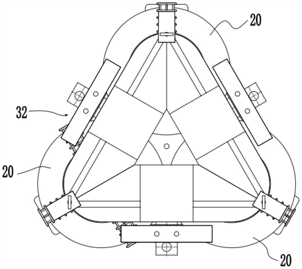
[0041] Embodiments of the present invention are described in detail below, and examples of the embodiments are shown in the drawings, wherein the same or similar reference numerals denote the same or similar elements or elements having the same or similar functions throughout. The embodiments described below by referring to the figures are exemplary only for explaining the present invention and should not be construed as limiting the present invention.

[0042] It should be understood that in the description of the present invention, the orientation descriptions, such as up, down, front, back, left, right, etc. indicated orientations or positional relationships are based on the orientations or positional relationships shown in the drawings, and are only for convenience The present invention is described and simplified descriptions do not indicate or imply that the device or element referred to must have a specific orientation, be constructed and operate in a specific orientatio...


PUM


Abstract

The invention discloses a clamping device of a three-dimensional wound core transformer and a transformer. The clamping device comprises a lower frame, a plurality of upper pressing plate assemblies and a plurality of screw assemblies, the lower frame is arranged on the lower sides of a plurality of coil windings of the three-dimensional wound core transformer, the upper pressing plate assemblies are distributed on the upper sides of the coil windings, the lower frame and the upper pressing plate assemblies are connected through the screw assemblies so as to jointly clamp the coil windings. The transformer provided by the embodiment of the invention, the clamping device is adopted; compared with a traditional clamping device, the clamping device of the invention can assist in reducing steel consumables at the periphery of the iron core, is simpler in structure, occupies a smaller space, is lighter in weight and saves materials and reduces stray loss of the transformer.

Description

technical field [0001] The invention relates to the technical field of power equipment, in particular to a clamping device for a three-dimensional wound core transformer and the transformer. Background technique [0002] Three-dimensional wound core transformers are more and more widely used due to their advantages of excellent performance, no-load loss and low noise level. [0003] In the related art, three-dimensional wound core transformers are usually equipped with clamping devices, which are used to provide support for the coil windings during the assembly and operation of the transformer, so as to avoid the displacement of the coil windings and affect the performance of the transformer, resulting in no-load loss and noise increase. [0004] The traditional clamping device mainly includes an upper clamp and a lower clamp, which are generally equilateral triangle frames. The upper clamp and the lower clamp are welded by steel plates or section steel. On the whole, the ...

Claims


Application Information

Patent Timeline
Patent Type & Authority Applications(China)
IPC IPC(8): H01F27/30H01F27/34
CPCH01F27/303H01F27/34H01F27/306H01F27/33H01F30/12H01F27/2455
Inventor 许凯旋梁庆宁杨剑波谭恒志黄嘉俊张景暖关卓文
Owner HAIHONG ELECTRIC CO LTD
Why Eureka
Try Eureka