Transformer and power generation system

A transformer and voltage technology, applied in transformer/inductor components, transformer/inductor coils/windings/connections, circuits, etc., can solve problems such as overheating of clips, large lead current, and high current lead magnetic field that cannot be ignored.

Inactive Publication Date: 2020-12-22
TBEA HENGYANG TRANSFORMERS
View PDF0 Cites 1 Cited by
  • Summary
  • Abstract
  • Description
  • Claims
  • Application Information

AI Technical Summary

Problems solved by technology

There are two major problems in the design and development of extra-large transformers: one is the large capacity, and the coil will generate a strong leakage magnetic field; the other is that the current of the coil is very large, especially the low-voltage current is as high as tens of thousands of amperes, so the current of the lead wire is very large

Method used


Image

  • Transformer and power generation system
  • Transformer and power generation system
  • Transformer and power generation system

Examples


Embodiment Construction

[0025] In order to facilitate the understanding of the present application, the present application will be described more fully below with reference to the relevant drawings. Embodiments of the application are given in the drawings. However, the present application can be embodied in many different forms and is not limited to the embodiments described herein. On the contrary, the purpose of providing these embodiments is to make the disclosure of this application more thorough and comprehensive.

[0026] Unless otherwise defined, all technical and scientific terms used herein have the same meaning as commonly understood by one of ordinary skill in the technical field to which this application belongs. The terms used herein in the specification of the application are only for the purpose of describing specific embodiments, and are not intended to limit the application.

[0027] It can be understood that the terms "first", "second" and the like used in this application may be...


PUM


Abstract

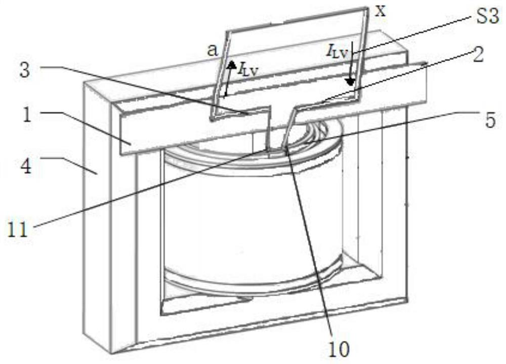
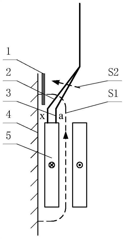
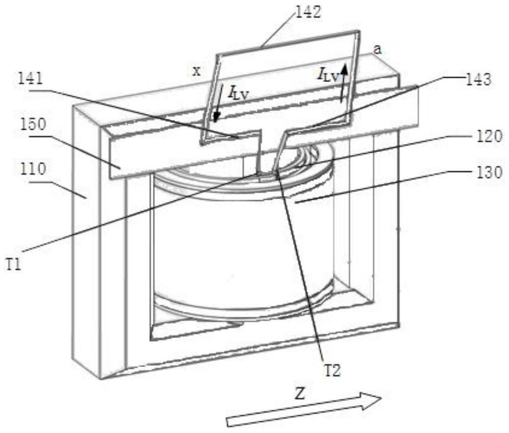
The invention relates to a transformer and a power generation system. The transformer comprises an iron core, a first coil, a second coil and a lead, wherein the first coil and the second coil are wound on the iron core; the first coil comprises a first terminal and a second terminal, the lead comprises a first line segment, a second line segment and a third line segment, a first end of the firstline segment is connected with the first terminal, a second end of the first line segment is connected with a first end of the third line segment through the second line segment, and a second end of the third line segment is connected with the second terminal; the winding direction of the first coil on the longitudinal section of the iron core is taken as a positive direction, wherein the windingdirection takes the first wiring end as a starting point; and the first line segment is located on the opposite side of the third line segment. The first line segment of the lead is located on the opposite side of the third line segment, so that the current direction of the lead is changed, the magnetic field direction generated by the current of the lead and the leakage magnetic field direction generated by the current of the first coil are opposite, a space magnetic field is restrained, stray losses are reduced, and local overheating of a clamping piece can be avoided.

Description

technical field [0001] The present application relates to the field of electric power technology, in particular to a transformer and a power generation system. Background technique [0002] A transformer is a device that uses the principle of electromagnetic induction to change the AC voltage, including an iron core (or magnetic core) and a coil, and the coil is wired through a lead wire. [0003] With the rapid development of my country's electric power industry, the demand for the capacity of generator sets is increasing, and the capacity of a single transformer used in conjunction with it is also increasing. There are two major problems in the design and development of extra-large transformers: one is the large capacity, and the coil will generate a strong leakage magnetic field; the other is that the current of the coil is very large, especially the low-voltage current is as high as tens of thousands of amperes, so the current of the lead wire is very large , the magnet...

Claims


Application Information

Patent Timeline
IPC IPC(8): H01F27/30H01F27/29
CPCH01F27/306H01F27/29
Inventor 苏钟焕阴祖强孙树波谭黎军詹小彬喻强胡伟王贵娟徐紫风欧强李中祥
Owner TBEA HENGYANG TRANSFORMERS
Why Eureka
Try Eureka