Single-phase self-starting permanent magnet synchronous motor

A permanent magnet synchronous motor, self-starting technology, applied to synchronous motors with static armatures and rotating magnets, synchronous machine parts, magnetic circuit static parts, etc., can solve the problem of reluctance torque and electromagnetic torque. Uniformity, reduced starting torque, unstable motor operation, etc., to achieve the effect of improving uniformity, improving magnetic field strength, and increasing magnetic field strength

Inactive Publication Date: 2012-11-28
SHANDONG UNIV OF SCI & TECH
View PDF0 Cites 1 Cited by
  • Summary
  • Abstract
  • Description
  • Claims
  • Application Information

AI Technical Summary

Problems solved by technology

[0010] 1. The shape of the pole arc on each side of the stator pole and the corresponding air gap length have a large asymmetry with respect to the center line of the stator pole. Although it is observed on the surface that such a design will increase the starting angle at static time, but when power is applied When starting, due to the influence of the asymmetric air gap length, the direction of the excitation field generated by the stator winding at the air gap is not in the direction of the centerline of the stator pole, which is generally considered to be the direction of the centerline of the stator pole, and the length of the air gap relative to the centerline of the stator pole is also smaller. , The direction of small reluctance deflects a certain angle, so that the actual starting angle decreases, the starting torque decreases, and the starting performance is poor
[0011] 2. Between the stator poles (perpendicular to the center line of the stator poles) are two large gaps without iron cores. Limited by this special structure, the reluctance torque is obviously uneven
When running with power on, the excitation field generated by the stator winding is a pulsating magnetic field acting between the stator poles. Simply according to the double-rotation theory, this pulsating magnetic field is decomposed into two opposite and uniform rotating magnetic fields within a range of 360°. Prejudice, because there is no iron core at the gap, it has great reluctance, so the decomposed rotating magnetic field is seriously uneven in the range of 360°, so that the electromagnetic torque is also uneven, reluctance torque and electromagnetic torque The unevenness of the motor itself has the defects of unstable operation, high vibration and noise, and the design of the stator magnetic pole shape and pole arc shape in the prior art has aggravated such defects
[0012] 3. At the same time, since the recovery permeability of permanent magnet materials such as ferrite is very small (the reluctance is very large), and when it is used as a driving motor for a micro pump, there must be a seal for isolation between the permanent magnet rotor and the stator poles. The sleeve (which constitutes a part of the pump casing, the permanent magnet rotor is inside the pump casing, and the stator is outside the pump casing) makes the air gap (the distance between the permanent magnet rotor and the stator poles) of this motor larger, so the motor's Flux leakage is large
The prior art does not fully realize this point, so there are defects in the structural design of the stator core, mainly because the stator poles do not protrude, so that the distance between the two U-shaped arms of the stator core other than the stator pole part and the magnetic resistance Relatively small, the leakage flux of the stator core is relatively large, the motor loss, especially the stray loss, is relatively large, and the comprehensive performance such as motor efficiency is reduced

Method used


Image

  • Single-phase self-starting permanent magnet synchronous motor
  • Single-phase self-starting permanent magnet synchronous motor

Examples


Embodiment Construction

[0046] The specific implementation manner of the present invention will be described below in conjunction with the accompanying drawings.

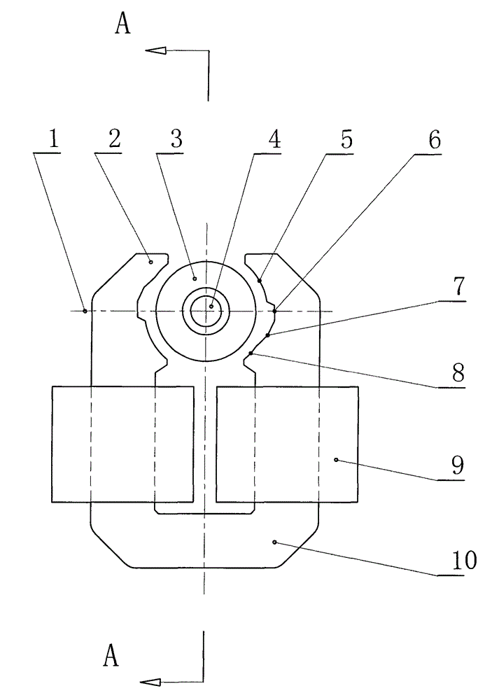
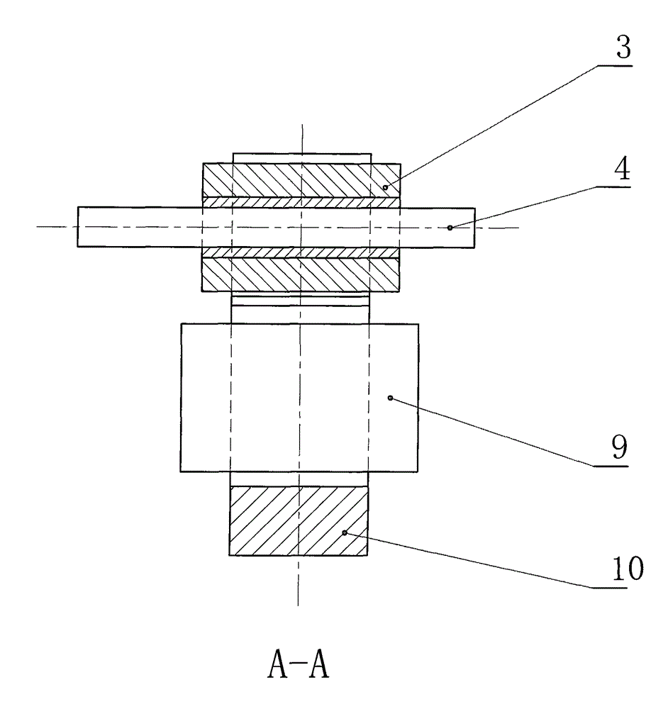
[0047] Depend on figure 1 , figure 2 Visible, the present invention is made of permanent magnet rotor (3), stator iron core (10) and stator winding (9), and permanent magnet rotor (3) is the cylindrical permanent magnet rotor of radial two-pole magnetization, and permanent magnet rotor (3 ) outside is a stator composed of a stator core (10) and a stator winding (9), the stator core (10) is U-shaped, the stator winding (9) is installed on the stator core (10), and grows out of the stator winding (9) The two ends of the stator core (10) are two opposite stator poles (2), and the inner side of the stator pole (2) is two opposite pole arcs, and the pole arcs on each side are not strictly arc-shaped, so that in the stator Non-uniform air gaps with different air gap lengths are formed on both sides of the pole center line (1), and the pole ar...


PUM


Abstract

The invention relates to a single-phase self-starting permanent magnet synchronous motor, which belongs to the field of micromotors, is used as a driving motor of a mini-type water pump, a cooling system of a vehicle engine and a driving motor of a warm air system circulating pump, and can also be used in other aspects. The invention aims to improve the starting performance and the operational performance, and is characterized in that the single-phase self-starting permanent magnet synchronous motor is provided with two protruding stator magnetic poles, the pole arc of the magnetic pole at each side consists of four sections, wherein the first section has the maximum length and minimum air gap length, the second section has the maximum air gap length and is at the point of a pole shoe centerline, the air gap length of the third section is gradually reduced, the length of the fourth section is smaller than or equal to 1 / 2 of that of the first section, and the air gap length of the fourth section is minimum.

Description

technical field [0001] The invention relates to a single-phase self-starting permanent magnet synchronous motor, belonging to the field of micro motors, which can be used as a driving motor for water pumps such as washing machines and dishwashers, and can also be used as a circulating pump for motor vehicle engine cooling systems and heating systems. Driving motors, driving motors for circulating pumps in liquid cooling systems of electronic equipment such as computers, can also be used in other aspects. Background technique [0002] This kind of motor is a special structure motor proposed in the 1970s. It uses a permanent magnet rotor and a U-shaped iron core, and relies on a special uneven air gap to start. [0003] The rotor of this motor is a permanent magnet rotor, usually made of ferrite permanent magnet material. Since the ferrite permanent magnet material has good corrosion resistance and can work stably for a long time in liquids such as water, when it is used as a...

Claims


Application Information

Patent Timeline
Patent Type & Authority Patents(China)
IPC IPC(8): H02K21/12H02K21/02H02K15/03H02K1/12
Inventor 于昊昱衣美凤于佳衣
Owner SHANDONG UNIV OF SCI & TECH
Why Eureka
Try Eureka