
pfc circuit and its control method

A control method and circuit technology, applied in the field of converters, can solve problems such as low conversion efficiency, achieve high conversion efficiency, and ensure the effect of zero-voltage switching

Active Publication Date: 2021-11-19
HUAYUAN SEMICON SHENZHEN LTD
View PDF6 Cites 0 Cited by
  • Summary
  • Abstract
  • Description
  • Claims
  • Application Information

AI Technical Summary

Problems solved by technology

[0005] The present invention provides a PFC circuit and its control method to solve the problem that the conversion efficiency of the PFC circuit will be adversely affected and may achieve lower conversion efficiency

Method used


Image

  • pfc circuit and its control method
  • pfc circuit and its control method
  • pfc circuit and its control method

Examples


Embodiment Construction

[0075] The following will clearly and completely describe the technical solutions in the embodiments of the present invention with reference to the accompanying drawings in the embodiments of the present invention. Obviously, the described embodiments are only some, not all, embodiments of the present invention. Based on the embodiments of the present invention, all other embodiments obtained by persons of ordinary skill in the art without making creative efforts belong to the protection scope of the present invention.

[0076] The terms "first", "second", "third", "fourth", etc. (if any) in the description and claims of the present invention and the above drawings are used to distinguish similar objects and not necessarily Describe a specific order or sequence. It is to be understood that the data so used are interchangeable under appropriate circumstances such that the embodiments of the invention described herein can be practiced in sequences other than those illustrated or...


PUM


Abstract

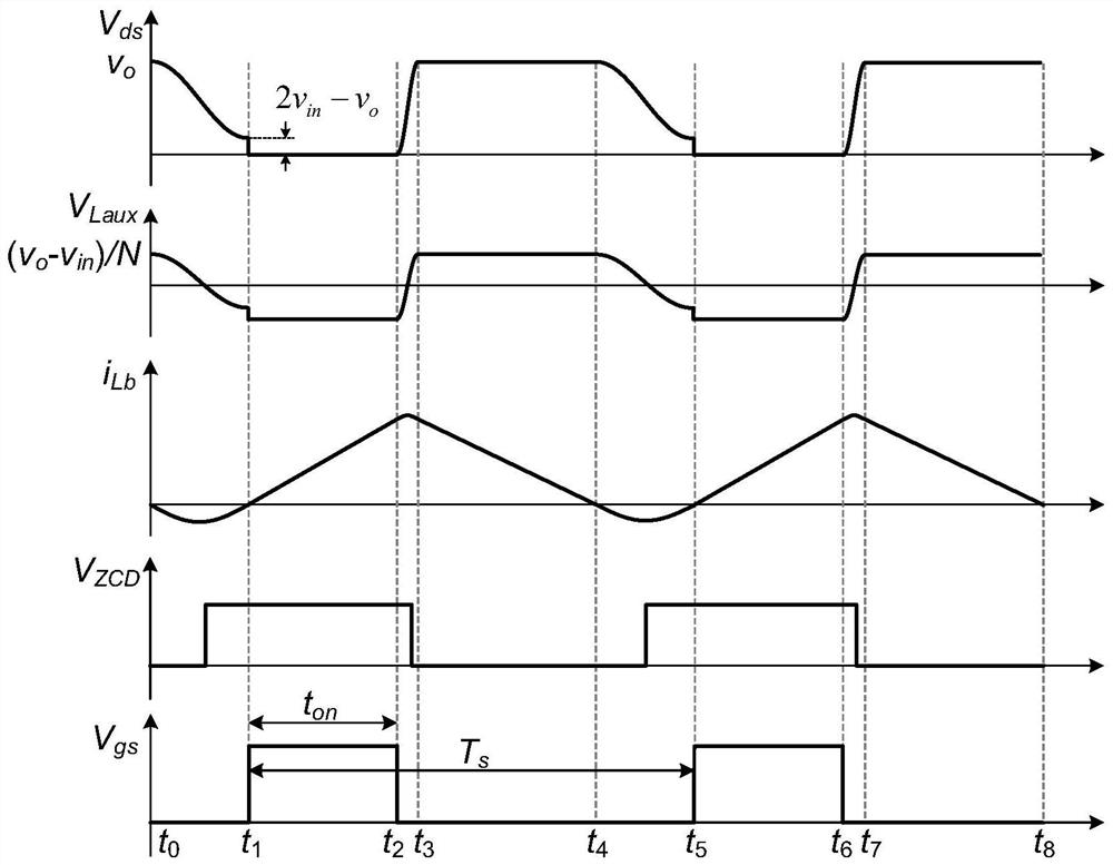
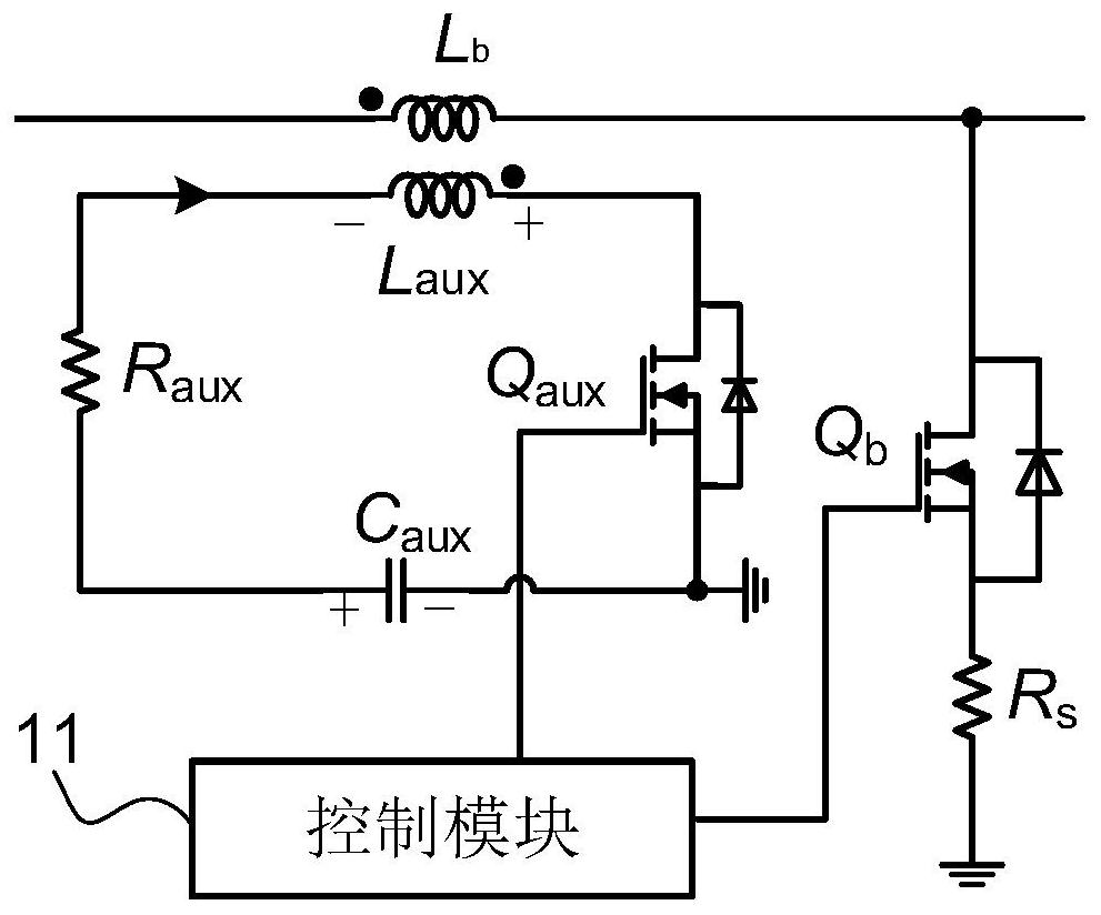
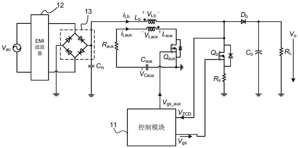
The present invention provides a PFC circuit and a control method thereof, wherein the PFC circuit includes: a Boost inductor, an auxiliary winding, an auxiliary switch tube, a main switch tube, a clamp capacitor, a series resistor and a control module; the Boost inductor and the The auxiliary winding mutual inductance, the first end of the auxiliary winding is connected to the first end of the auxiliary switch tube, the second end of the auxiliary switch tube is connected to the first end of the clamp capacitor, and the clamp capacitor The second end is connected to the first end of the series resistor, and the second end of the series resistor is connected to the second end of the auxiliary winding; the main switch tube is connected between the Boost inductor and ground; the control The modules are respectively connected to the control terminal of the main switch tube and the control terminal of the auxiliary switch tube.

Description

technical field [0001] The invention relates to the field of converters, in particular to a PFC circuit and a control method thereof. Background technique [0002] The PFC circuit can be understood as a power factor correction circuit, wherein the PFC circuit can specifically implement step-up power factor correction. Meanwhile, the PFC circuit can have multiple working modes, such as CRM mode and DCM mode. [0003] Among them, the PFC circuit may include a Boost inductor and a main switch tube; in CRM mode, when the bus voltage of the PFC circuit is high (for example, when it is greater than half of the output voltage), only valley switching can be realized by controlling the main switch tube. (that is, control the main switch to turn on when the source-drain voltage of the main switch is at the bottom), because the bus voltage is high, the source-drain voltage does not reach the zero point when it is at the bottom, and then the control of the main switch cannot be realize...

Claims


Application Information

Patent Timeline
Patent Type & Authority Patents(China)
IPC IPC(8): H02M1/42H02M1/08
CPCH02M1/42H02M1/4225H02M1/083H02M1/0058H02M1/0006H02M1/0064H02M1/344H02M1/4266
Inventor 李林凯郭春明胡鹏
Owner HUAYUAN SEMICON SHENZHEN LTD
Learn More