Video image component prediction method and device, and computer storage medium

A technology for video images and prediction methods, which is applied in the directions of image communication, digital video signal modification, electrical components, etc., can solve the problems of reducing the prediction accuracy of the chrominance prediction value of the coding block, and the factors are not comprehensive enough.

Active Publication Date: 2021-07-16
GUANGDONG OPPO MOBILE TELECOMM CORP LTD
View PDF8 Cites 0 Cited by
  • Summary
  • Abstract
  • Description
  • Claims
  • Application Information

AI Technical Summary

Problems solved by technology

[0004] However, when constructing the linear model, the factors considered are not comprehensive enough. For example, when predicting the chromaticity value with the luminance value, most of them consider the factors of the adjacent reference luminance value and the adjacent reference chromaticity value; When predicting between chroma values, most of them consider the factors of adjacent reference chroma components
Therefore, once there is a large deviation between the adjacent reference luma value and the parameter corresponding to the current coding block, or there is a large deviation between the adjacent reference chrominance component and the parameter corresponding to the current coding block, the calculated linear model will be different from The expected model deviates, which reduces the prediction accuracy of the chroma prediction value of the current coding block, causing a large deviation between the chroma prediction value and the real chroma value

Method used


Image

  • Video image component prediction method and device, and computer storage medium
  • Video image component prediction method and device, and computer storage medium
  • Video image component prediction method and device, and computer storage medium

Examples


Embodiment 1

[0047] An embodiment of the present application provides a method for predicting video image components, Figure 7 It is a schematic diagram of the implementation flow of a method for predicting video image components proposed in the embodiment of the present application, as shown in Figure 7 As shown, in the embodiment of the present application, the method for the prediction device to perform video image component prediction may include the following steps:

[0048] Step 101. Obtain the first image component adjacent reference value and the first image component reconstruction value corresponding to the current encoding block; wherein, the first image component adjacent reference value is used to represent the first image component corresponding to the adjacent reference point of the current encoding block. Image component parameters, the reconstruction value of the first image component is used to characterize the reconstruction parameters of one or more first image compon...

Embodiment 2

[0081] Based on the first embodiment above, in the embodiment of the present application, the method for determining the correlation coefficient by the above-mentioned prediction device according to the adjacent reference value of the first image component and the reconstruction value of the first image component may include the following steps:

[0082] Step 102a, performing a difference operation on any one of the adjacent reference values ​​of the first image component and each reconstructed value of the first image component to obtain a component difference corresponding to any one of the reference values; wherein, a first image The component adjacent reference value and a reconstructed value of a first image component correspond to a difference value.

[0083] In an embodiment of the present application, after the prediction device obtains the adjacent reference value of the first image component corresponding to the current coding block and the reconstructed value of the ...

Embodiment 3

[0100] Based on the above-mentioned first embodiment, in the embodiment of the present application, before the above-mentioned prediction device determines the scale factor according to the above-mentioned weight coefficient, that is, before step 104, the method for the above-mentioned prediction device to perform video image component prediction may further include the following steps:

[0101] Step 107. Obtain the adjacent reference value of the second image component corresponding to the current coding block; wherein, the adjacent reference value of the second image component is a second component parameter corresponding to the adjacent reference point and different from the first image component parameter.

[0102] In an embodiment of the present application, before the prediction device determines the scale factor according to the weight coefficient, it may first acquire the adjacent reference value of the second image component corresponding to the current coding block.

...


PUM


Abstract

The embodiment of the invention discloses a video image component prediction method and device, and a computer storage medium. The prediction method comprises the following steps: acquiring a first image component adjacent reference value and a first image component reconstruction value corresponding to a current coding block, wherein the first image component adjacent reference value is used for characterizing a first image component parameter corresponding to an adjacent reference point of the current coding block, and the first image component reconstruction value is used for characterizing a reconstruction parameter of one or more first image components corresponding to the current coding block; determining a correlation coefficient according to the first image component adjacent reference value and the first image component reconstruction value, wherein the correlation coefficient is used for characterizing the image component deviation degree between the current coding block and the adjacent reference point; inputting the correlation coefficients into a preset weight calculation model to obtain a weight coefficient corresponding to the adjacent reference point; determining a scale factor according to the weight coefficient; and obtaining a second image component predicted value corresponding to the current coding block through the scale factor.

Description

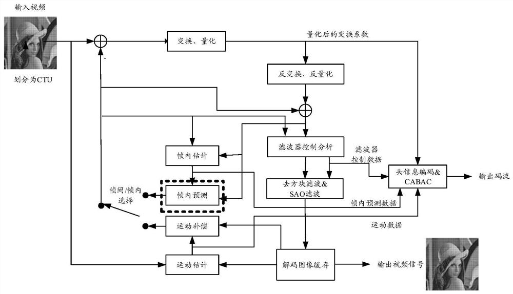
[0001] This application is a PCT international patent application PCT / CN2018 / 099703 with an application date of August 9, 2018, which entered the Chinese national phase. The Chinese patent application number 201880096257.8, the title of the invention is "Prediction method and device for video image components, and computer storage medium " divisional application. technical field [0002] Embodiments of the present application relate to intra-frame prediction technologies in the field of video coding, and in particular, to a method and device for predicting video image components, and a computer storage medium. Background technique [0003] In the next-generation video coding standard H.266 or Versatile Video Coding (VVC), the color component linear model prediction method (Cross-component Linear Model Prediction, CCLM) can be used to realize the brightness value to chroma value or color The prediction between luminance values, specifically, the linear regression method can b...

Claims


Application Information

Patent Timeline
IPC IPC(8): H04N19/105H04N19/136H04N19/182H04N19/186H04N19/593
CPCH04N19/105H04N19/136H04N19/182H04N19/186H04N19/593H04N19/124H04N19/126H04N19/13H04N19/159H04N19/176H04N19/50H04N19/82H04N19/86
Inventor 霍俊彦柴小燕马彦卓杨付正
Owner GUANGDONG OPPO MOBILE TELECOMM CORP LTD
Why Eureka
Try Eureka