Light guide plate, preparation method of light guide plate and backlight module

A technology of light guide plate and substrate, applied in the fields of light guide plate, preparation of light guide plate, optical components and backlight modules, can solve the problems of insufficient scratch resistance and low production yield, and achieve high assembly yield and high production efficiency , the preparation method is simple

Pending Publication Date: 2021-07-20
ZHANGJIAGANG KANGDE XIN OPTRONICS MATERIAL
View PDF0 Cites 1 Cited by
  • Summary
  • Abstract
  • Description
  • Claims
  • Application Information

AI Technical Summary

Problems solved by technology

[0004] At present, the improvement of the light guide plate is mainly focused on the bottom surface structure of the light guide plate, focusing on improving the light uniformity of the backlight module, while the light output surface of the light guide plate still adopts the injection-molded prism or lenti structure, because the light guide plate is mostly made of polycarbonate, etc. Plastic material, therefore, the scratch resistance is insufficient, and the production yield is low

Method used


Image

  • Light guide plate, preparation method of light guide plate and backlight module
  • Light guide plate, preparation method of light guide plate and backlight module
  • Light guide plate, preparation method of light guide plate and backlight module

Examples


Embodiment Construction

[0033] The present invention will be described in detail below in conjunction with various embodiments shown in the drawings. However, these embodiments do not limit the present invention, and any structural, method, or functional changes made by those skilled in the art according to these embodiments are included in the protection scope of the present invention.

[0034] It should be understood that although the terms first, second, etc. may be used herein to describe various elements or structures, these described objects should not be limited by these terms. These terms are only used to distinguish these described objects from one another. For example, a first microstructure may be referred to as a second microstructure, and similarly, the second microstructure may also be referred to as the first microstructure, which does not depart from the scope of protection of the present application.

[0035] In the drawings, the thickness of layers, films, panels, regions, etc., ar...


PUM

PropertyMeasurementUnit
widthaaaaaaaaaa
depthaaaaaaaaaa
radiusaaaaaaaaaa

Abstract

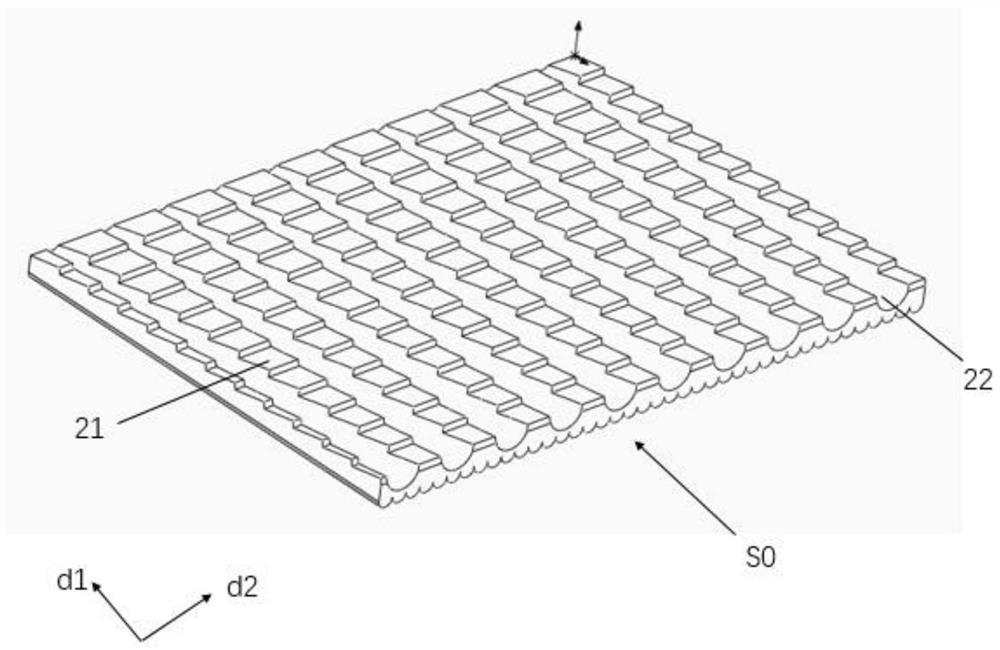
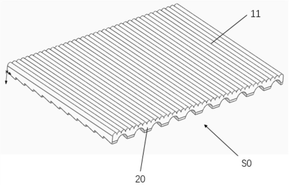
The invention provides a light guide plate, a preparation method of the light guide plate and a backlight module, the light guide plate comprises a first substrate and a gradual change microstructure arranged on the first substrate, and one surface, far away from the first substrate, of the gradual change microstructure is a light emitting surface S1 of the light guide plate; one surface, far away from the gradual change microstructure, of the first substrate is a bottom surface S2 of the light guide plate, and a light incident surface S0 is connected with the light emergent surface S1 and the bottom surface S2; and the gradually-changed microstructure gradually changes from sparse to dense along with the distance from the light incident surface S0. According to the light guide plate, the light-emitting surface of the light guide plate is impressed by the light-cured resin to form the gradual change microstructure, the visual angle can be converged, the brightness of a backlight module is improved, a certain privacy protection effect is achieved, and compared with an integrally-formed light guide plate, the light guide plate has more excellent scratch resistance. The invention further provides a preparation method of the light guide plate. The light guide plate has the advantages of being low in mold opening cost, higher in production and assembly yield and the like.

Description

technical field [0001] The invention relates to an optical element and a backlight module, in particular to a light guide plate, a preparation method of the light guide plate and a backlight module. Background technique [0002] Backlight modules are mainly divided into direct-lit backlight modules and side-lit backlight modules according to the location of the light source. Taking the side-illuminated backlight module as an example, it usually includes a light guide plate and a light source disposed on the side of the light guide plate. After the light emitted by the light source enters the light guide plate, the light will be confined in the light guide plate due to total reflection. [0003] In the known technology, the bottom surface of the light guide plate is a dot structure with varying densities to destroy the total reflection, and the light can be smoothly emitted from the light-emitting surface of the light-guide plate. structure. The upper surface of the light ...

Claims


Application Information

Patent Timeline
Patent Type & Authority Applications(China)
IPC IPC(8): G02B6/00
CPCG02B6/0043G02B6/0053G02B6/0055G02B6/0058G02B6/0065
Inventor 李敏敏
Owner ZHANGJIAGANG KANGDE XIN OPTRONICS MATERIAL
Why Eureka
Try Eureka